These procedure notes have been have been written to assist VA owners in replacing their King Pins. The king pins and bushes are Safety Critical Items on your car and their replacement should only be undertaken by a competent person.
Please read through all the procedure before undertaking the work.
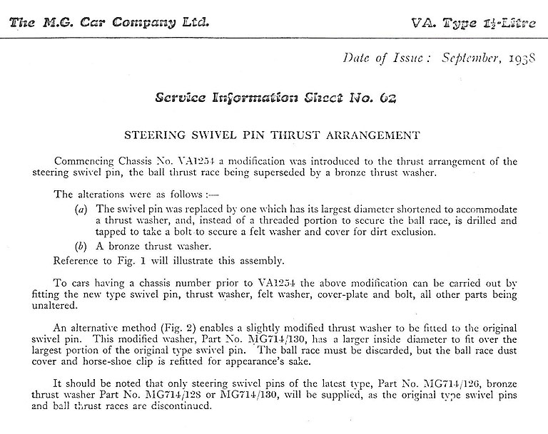
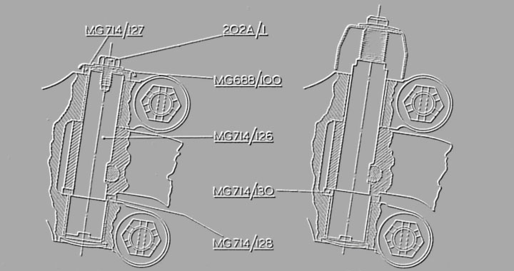
The original king pins fitted to the VA (up to chassis VA1254) have a threaded section at the top that secured a thrust bearing. These were discontinued in February 1938 by the factory due to complaints of wheel wobble. A service information sheet was issued to dealers/service departments to enable them to deal with complaints of wheel wobble from owners. The thrust bearing at the top of the king pin was replaced by a bronze thrust washer fitted between the axle beam eye and the king pin bottom bush. Copy of Service Information Sheet No. 62 is below. This change transfers the front weight of the car from the top of the king pin to the bottom.
NOTE – There are still some of these early king pins in circulation as new old stock; whilst the king pin and bushes can still be used the thrust bearing should be discarded and a modified thrust washer used.
The king pins fitted to the VA are unusual in that they are stepped with the bottom end 0.060 inches larger than the top end, which complicates reaming the bushes out.
With our cars now being over 80 years old they may not have been regularly serviced, especially during the 1960s when they were ‘old bangers’ bought cheaply and run on a shoe string with little regard to maintenance. As a result of this there can be wear in the axle beam and the steering knuckles, hence there are some additional checks included below that are not in the workshop manual.
Before commencing the task it is worth purchasing a digital Vernier caliper (about £30 in the UK from Halfords or Moss) or hiring or borrowing one if you do not own one. This is to measure the wear on the axle beam and steering knuckles. The other special tools required are a hub puller and a ball joint separator.
A variety of shims will be required which should be obtained in advance. These need an internal diameter of 21mm and external diameter as close to 38mm as possible. Typically the bronze thrust washer supplied with the king pin set is 3mm thick. TIP: MGB king pin shims come as a set of three, 0.055”, 0.060” and 0.065” but have a smaller internal diameter and therefore need enlarging if nothing else is available. The closest off-the-shelf shims seem to have an internal diameter of 22mm and an external diameter of 32mm, which is not ideal.
- Jack up car and support the front axle beam on axle stands.
- Remove the wheel.
- Remove the brake drum and also the front hub.
- Disconnect steering drag link and track tie bar ball joints from steering knuckle.
- Remove brake back plate complete with brake shoes and hydraulics and tie to chassis ensuring no load on the hydraulic hose.
- Remove the cotter pin securing the king pin (slacken off the nut, use a pin punch to loosen cotter pin then remove the nut and the cotter pin). Do not hammer the thread in case you have to reuse it.
- Remove king pin (this should be a push fit and not require excessive force, if it has rusted in soak in penetrating oil allowing time for it to penetrate before driving the pin out from the top) and then remove the steering knuckle.
- Clean the king pin hole in the axle and trial fit the new king pin. It should be a tight hand push fit without using any tools. If it is tight because of rust the hole should be cleaned up using the correct sized reamer (an adjustable reamer is also suitable). If the king pin is very loose and ‘rocks’ the axle requires replacing or the hole bushed (see Issue 23 SVW Review 2014 page 8). This is a specialist task and it would be prudent to have the axle crack tested before the machining for the bushes is undertaken.
- Use a straight edge to check the faces of the axle are flat and take measurements with a Vernier caliper or micrometer at three or four positions to check that they are parallel and square to the king pin. If the faces are not parallel they can be filed flat taking care to measure frequently. If the axle is being re-bushed the faces could be lightly machine skimmed at the same time if required.
- Press out the king pin bushes from the steering knuckle.
TIP – Use a length of threaded rod, large washers and two sockets one slightly smaller than the bush and one that the bush will go inside and then simply tighten the nuts to push the bush out. Do this on each arm of the steering knuckle and not across the arms as this puts undue stress on the arms. - Remove the grease nipples and clean the steering knuckle.
- Press in the new king pin bushes, the threaded rod can be used again for this and the old bush used in place of the smaller socket.
NOTE – There are various designs of bushes some with lubrication holes and grooves, some a top hat shape negating the need for the thrust washer, and some just plain bushes. If they have a lubrication hole ensure this lines up with the grease nipple hole. If they have lubrication groves these should face inward to the axle beam. If they do not have a lubrication hole, drill one through the grease nipple hole taking care not to damage the threads. - Use a straight edge to check the inside faces of the steering knuckle are flat and take measurements with a Vernier caliper or internal micrometer at three or four positions to check that they are parallel. If the faces are not parallel they can be filed flat taking care to measure frequently and ensure they are square to the king pin. The outside faces do not require checking.
- There are two methods of checking if the thrust washer is the correct thickness to allow for the maximum 0.004 inch clearance.
a) Measure the distance between the inner faces of the steering knuckle (A), deduct the measurement across the faces of the axle (B), and also deduct the maximum clearance 0.004 inches, this gives the thickness of the thrust washer required.
A – B – 0.004 = Thickness of washer
b) Assemble the steering knuckle and thrust washer on to the axle without the king pin and measure the clearance with feeler gauges. If it exceeds the maximum 0.004 inches then a new or additional thrust washer or shims will be required.
If a new or additional thrust washer are required it’s preferable that these are of bronze however steel ones can be used. The position of the king pin and hence the size of the packing washers / shims (top and bottom) is dictated by the position of the cotter pin. Several trial fits may be required to achieve the correct clearance.
NOTE – The large end of the king pin should be a sliding fit inside the thrust washer.
TIP 1 – If you have to reduce the thickness of a washer and do not have access to a lathe place a sheet of course emery paper on a flat surface and rub down the washer using a circular motion, finishing off with fine emery paper. This is tedious but it works.
TIP 2 – To assist lubrication of the faces, use a junior hacksaw to cut a very shallow cross on one side and a second cross at 45 degrees to the first cross on the other side of the thrust washer. Such oil grooves only require a depth of about 0.5mm and should breach the inner diameter of the washer but not the outer diameter. It may be simpler to make a circular cut in the washer (see photo), with the same on the obverse but offset 180 degrees. - Use a stepped reamer to ream out the new bushes, the king pin should be a hand push fit without the use of tools. If a stepped reamer is not available use normal or adjustable reamers ensuring that the holes line up perfectly. If the stepped reamer used is slightly worn it may be required afterwards to work the bush gently with emery paper to achieve a perfect fit.
- Thoroughly clean axle eye, steering shackle, king pin, and thrust washer.
Replace grease nipples. Lightly grease the king pin, bushes, thrust washer, and mating faces. Reassemble ensuring the flat on the king pin is in line with the cotter pin hole and the thrust washer is at the bottom. Replace cotter pin and secure with the washer and nut (on some king pins there is a slot at the bottom to assist in lining up the flat on the king pin with the cotter pin hole). Check that the steering shackle moves freely by hand over all its travel. Use a grease gun to lubricate the steering shackle, some grease should emerge around the thrust washer.
TIP – If new cotter pins were not supplied in the king pin set they can be obtained from motorcycle or bicycle dealers, the ‘flat’ may requiring filing to ensure enough thread protrudes to fit the nut and washer.
If the existing pin has to be reused, remove any burrs from the ‘flat’ with a file before reusing and also remove any corrosion on the exposed end.
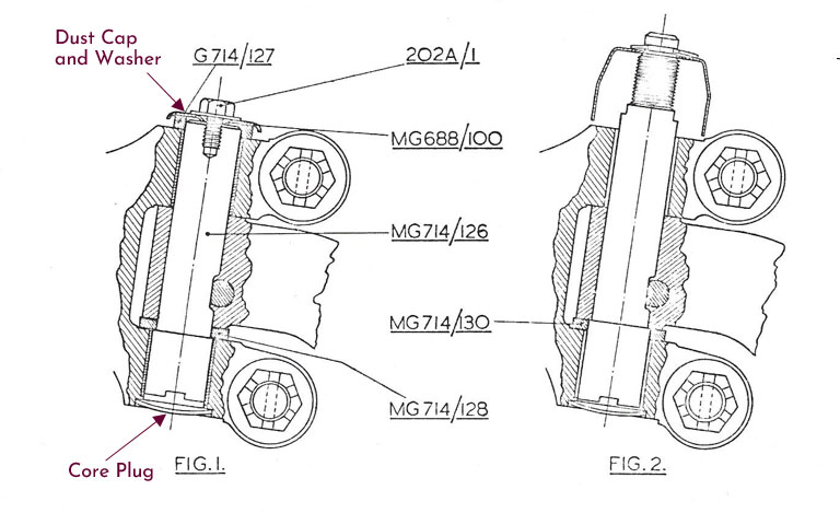
NOTE – With some king pin sets there is a cap and felt washer that fits to the top of the king pin and a ‘core plug’ that fits into the bottom of the steering shackle (see figure 1 on the Service Information Sheet no. 62) – these are to keep dirt out. - Replace brake back plate.
- Reconnect steering drag link and track tie bar ball joints using new nylock nuts or new split pins if castellated nuts are used.
- Replace front hub using a new split pin.
- Replace brake drum and wheel and then check there is no movement in any direction before taking the car off the axle stands.
Road test and enjoy VA Motoring again!