THE MOTOR TRADER April 7, 1937 – “TRADER” SERVICE DATA No. 12
Servicing the M.G. Two-Litre
Described as a fast touring car the M.G. 2-litre will, when kept in condition, give a very good performance indeed. It is essential that the various factors upon which tune depends receive proper attention.
Actually the car, for all its performance, is reliable and by no means delicate, so that a little regular attention is all that is required between major servicing. Adjustment and clearances, as specified, should be adhered to, as M.G. experience makes it unlikely that a trader can improve upon recommendations.
Engine
General
Six cylinders cast en bloc with deep skirt, mounted fairly hard on rubber front and rear. To remove, the engine must be lifted 5in. to clear engine bolts. General layout consists of overhead valves with light push-rod and rockers. Timing by chain at front end. Three-pulley belt for fan, impellor and dynamo. Clutch and gear box in unit. Remote control.
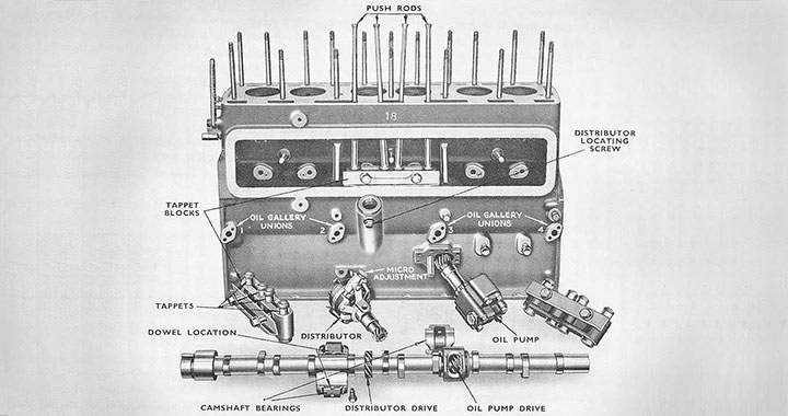
Camshaft
At near side, four bearings. Table base tappets carried in three blocks of four. If engine is right way up these blocks must be removed before shaft can be drawn, as tappets will foul the cams. To remove shaft, remove oil pump and distributor to release skew gears.
Remove timing chain and sprockets and draw shaft forward. It will pass through the front bearing and leave the rear bearing, but middle bearings must come away. Release dowel screws of middle bearings and wire two halves to camshaft, using grooves in ends. Draw shaft until bearings are clear, untie, and pull out shaft. To replace, insert shaft until it is necessary to insert second and third bearings. Tie these to shaft and untie when sufficiently near home. Move bearings until with a wire or blunt scriber locating holes are found to register with lock screw holes.
Timing
By roller chain at front end. One tooth on engine and on the camshaft sprocket marked with T. Chain has two white links marked T. Place marks to register, with short side of chain uppermost.
On front end of crankshaft is a damper embodying starter dog and fan pulley. T.D.C. mark (small hole) on rear inner face of pulley in line with arrow on timing cover. To remove chain both sprockets must be drawn together. Sprockets keyed to shafts. Inlet opens 11 deg. early with clearance of 0.015in. Otherwise inlet opens 27.8 mm. before T.D.C. measured on flywheel rim. Contacts open 7 deg. before T.D.C. on full retard.
Valves
Not interchangeable, the exhaust having a smaller head. Head diameter, exhaust, 30 mm., inlet 33 mm.; port diameter 26 mm. and 30.5 mm.; stem diameter 8 mm.; overall length 122.3 mm.; lift 10 mm. face angle 45 deg.
Valve guides are push fit from above. Clearance on stem 0.003in. Oiled plugs caused by worn guides. True valve seatings when guides are renewed.
Tappet clearance 0.0155in. both valves when warm. Adjustment on rockers. Split-cone cotters to valves.
Tappets
In blocks of four, dowelled and bolted to block. Circlip at top prevents tappet falling down through guide. Screws to be wired after replacement.
Crankshaft
Four bearings with detachable white metal linings, 55 mm. diameter, 41 mm. long. Shells are dowelled in caps. Upper shells free to mate against lower shell faces.
If necessary, shaft can be dropped with engine in place, but better to remove for work on crankshaft.
End float on shaft about 0.004in., but there is ample clearance and this tolerance is not held.
Radial clearance is held by fitting correct bearing. No work is necessary when fitting, and when shaft has been reground by factory undersize bearings are standard fit.
Palm on rear end of shaft receives flywheel. Front end parallel, with keyway.
Connecting Rods
Big ends direct metalled. If slack, exchange rods. Do not take up by filing. Big-end bolts flat topped and chamfered. Nuts castellated.
Gudgeon pin locked in small end by pinch bolt. Note that on same side of rod as pinch bolt is an oil-spray hole in big end shoulder. This must be to off side to spray walls. Big end diameter 48 mm., length 30 mm.
End float 0.004in. to 0.002in. Replacement rods are correct for standard shaft. If shaft has been reground rods are bored to standard undersize. Do not hand scrape or let two halves together. Big end is comparatively easy fit on crankpin.
Bore is too narrow to pass big ends, therefore piston must be assembled and pushed up from below.
Bore is too narrow to pass big ends, therefore piston must be assembled and pushed up from below.
| IMPORTANT FIGURES | |
|---|---|
| M.G. TWO-LITRE | |
| No. of cylinders | 6 |
| Bore and stroke (mm.) | 69 x 102 |
| Capacity (c.c.) | 2,288 |
| R.A.C. rating | 17.71 |
| Compression ratio | 6.5 |
| Firing order | 153624 |
| Valve clearance, hot, inlet and exhaust | 0.015” |
| Valve lift, (mm.) | 10 |
| Breaker gap | 0.010”- 0.012” |
| Plugs, Champion L10 14mm, gap | 0.018” |
| Gear box ratio | 4.75 |
| 6.55 | |
| 10.11 | |
| and 17.86 to 1 | |
| Rear axle ratio | 4.75 to 1 |
| Capacity: | |
| Sump, gallons | 2 ½ |
| Gear box, pints | 2 ¼ |
| Rear axle, pints | 2 |
| Petrol tank, gallons | 10 |
| Radiator, gallons | 2 7/8 |
| Tyres and pressures | 5.50” x 18”, 30 lbs. |
| Wheelbase | 10’ 3” |
| Track | 4’ 5 ½” |
| Turning circle | 40ft. |
| Weight | 29 ½ cwt. |
Pistons
Two types of piston will be found. The first ceased at Engine No. Q.P.H.G. 1165. It had four rings, two compression and a slotted scraper above the pin and a bevelled scraper, pegged, in the skirt. Bores are marked A, B, or C, with an added figure, A+0, A+5, and so on, the figure showing hundredths of a millimeter. A+5 equals 69.05 mm. Pistons are marked “A” plus or minus a figure, representing actual dimensions. To provide 0.11 mm. clearance a piston to fit an A + 0 bore would be marked A-0.11 or 68.89 actual.
The second type – Q.P.H.G. 1166 onwards was of the same bore, but was Aerolite with two compression and one slotted scraper above the pin. This was marked to show the bore it fitted, clearance having already been allowed. Thus A + OK fits an A + 0 bore, and A +1 fits A+1 (69.01 mm.) bore, the clearance being allowed for.
When clamping rod on gudgeon pin rod must not be held in the vice or it may be twisted or bent. M.G. practice is to use a pair of thimbles, turned down to a snug fit in the pin and pin holes and standing well proud. If these are gripped in a vice all stress lies along the pin and the piston or rod will not be distorted.
Carburettor
S.U., two, with balancing pipe. CH needles. Alternatives are CL for richer, CK for weaker.
Four causes of trouble only: Piston may be sticking due to dirt on suction disc or piston or to bent needle; dirt or water in carburettor; deranged float mechanism causing flooding; carburettors not synchronised. In curing trouble, points to avoid are removing the jet, using a needle not absolutely straight; grinding the needle seat; and bending the fork to adjust jet level.
Fuel Feed
S.U. petrol pump as previously described. Rear petrol tank holds ro gallons. Fuel: Benzol mixture, Cleveland Discol, Ethylised fuels. With straight petrol retard spark on micrometer.
Flywheel
Spigoted and bolted to crankshaft palm. Integral starter ring of 9.46 : 1 ratio.
Ignition
Automatic governor, opening 7 deg. early below 600 r.p.m. Effective range of control 30 deg. (crankshaft) between 600 and 2,300 r.p.m. Distributor skew-driven off camshaft. Whole unit retained in boss on crankcase by set screw. Micrometer adjustment to advance or retard.
Give a few anticlock turns to prevent pinking if using straight No. 1 petrol. Condenser in head.
Dynamo
Lucas 12-volt C.V.C. Belt-driven.
Battery
Lucas 6o a.h., two 6-volts below rear seat. Positive earth. Sp. Gr. 1.250 to 1.300 full charged.
Starter
Bowden control for switch.
Water Circulation
By impellor driven by fan belt. Adjustment by moving dynamo. Water capacity 27/8 gallons. Thermostat in water-outlet pipe opens at 80 deg. C. Drain plug on radiator does not completely empty system. On off side of crankcase at rear is a second cock for draining the cylinders. Water impellor can be removed easily, and in case of trouble should be exchanged.
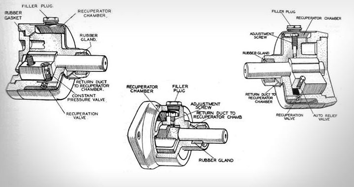
Lubrication
By positive gear pump skew-driven off camshaft in line with distributor, 2 ½ gallons of oil in circulation through Tecalemit oil cleaner. Aluminium sump ribbed. Filler in valve cover. Dipstick and electric gauge on sump, reading on dash.
Spring – loaded pressure – release valve, non-adjustable; running pressure 40-60 lb.
Oil passes to pump through a gauze filter and is circulated through the Tecalemit cleaner. (Renew element after first 1,000 miles and every 10,000 miles). Oil passes to external gallery, whence, by holes drilled in casting, to camshaft bearings and mains. Crankshaft drilled for pressure feed to big-ends. Forward camshaft bearing has a leak on to thrust face of camshaft chain wheel in which are holes to take oil to links. From rear main a hole in centre of crankshaft feeds the clutch, oil escaping through gauze windows in the clutch housing to be picked up by starter-ring teeth and thrown on to a gallery, whence it drains back to sump. Pipe at rear of engine has T piece, one side going to dashboard gauge and other to lubricate rocker-shaft gear.
Transmission
Clutch
Cork insert running in oil in clutch housing from engine. Undo ring of bolts to release clutch as complete unit. Remove circlips from three studs projecting through driven plate. It is not worth while recorking plate. Fit new plate.
To dismantle clutch, remove ring nut from hub of pressure plate, releasing ball race and washer.
Clutch pedal must have 1in. minimum free travel. Adjustments at bottom of pedal. Maximum travel controlled by adjustable stop and should coincide with clutch ceasing to spin.
Gear box
As the rear engine mounting is taken on the flywheel housing, clutch pit and gear box can be removed without supporting the engine. Note that gear box must be turned clockwise until the clutch control lever is free to swing horizontally under the sump as the box is withdrawn.
Then pull back until first motion shaft is free of clutch and lift out.
Synchromesh on third and top gears, and there are two forms of remote control. In other respects boxes are alike. When removing selector rods catch detent and locking balls as they are freed. Press down spring-loaded plunger and turn splined retaining plate at rear face on third-speed double helical gear until gear is free to slide on mainshaft. Mainshaft with rear ball race and washers can be withdrawn backwards, each gear being removed as freed. Grub screw locks layshaft and locking screw the reverse shaft.
Remove clutch pit with front oil seal and lift out ball-bearing packing washer for first motion shaft. Remove circlip in front of ball bearing and press out first motion-shaft assembly.
In dismantling synchromesh, the striking dog for top and third gears is retained on the sliding hub by three balls and springs. Apply sufficient effort to overcome these springs to push the hub out of the striking dog.
In reassembling, points to remember: Roller bearings and distance tube to be fitted into layshaft cluster; fit plunger and spring into mainshaft; lock third-speed double helical gear by turning locking plate in its groove in mainshaft until plunger engages; fit balls and springs underneath selector shafts and one ball between each shaft.
Rear Axle
Semi-floating spiral bevel, 4.75: 1 ratio. Pinion assembly, with journal and thrust bearings, screws into housing which is split and pinch- bolted, with lock tab for castellations. Shims on distance tube to take up slack. Pinion should spin freely without end play. Propeller-shaft flange, with oil seal, pulled against outer race by pinned castellated nut.
Drive housing, with crown wheel and differential, bolts to banjo casing. Gears can be meshed on bench. Differential ball races held in bearing caps so that by turning one adjusting nut or the other the crown wheel can be set in correct relation to centre line of pinion without any side movement, though free to spin. Adjustment of bearing can be made from back by removing pressed-steel cover plate.
Pinion can be entered or withdrawn from engagement by the castellations on the sleeve.
Approximate position is when inner edges of teeth on both wheels form unbroken surface with a tooth clearance of 0.007in. to 0.0010in. Unit can, in general, be dismantled without upsetting adjustment.
To draw half-shafts, whether axle is in place or not, remove wheels, unbolt and remove brake drums, replace hub nut and drive out half-shafts by hitting ears of nut with copper hammer.
When half-shafts are removed and propeller-shaft rear coupling is detached, drive assembly can be lifted out.
To remove axle from chassis, point to note is that springs are so steeply cambered when light that it is impossible to mate with pins. When all is ready, load car until springs are nearly flat, then put a stout beam below axle in line with springs and lash spring down to beam at ends. Remove ballast, remove front spring pin, and lower shackle pin and lift car off the axle.
If the springs have been allowed to go free and no suitable cramp is available it is best to strip spring and fit it to the car one leaf at a time, using two jacks to squeeze the lower leaves upwards.
To remove rear axle bearings, remove half-shaft, release tab washer on bearing securing nut, undo nut. Housing with bearings can then be withdrawn, using a suitable puller.
Propellor-Shaft
Hardy Spicer with needle roller joints. Only attention is to lubricate splines. In removing and dismantling see that all goes back in same position. Care needed not to distort flange yokes. If parts are not assembled in original positions, axle will be “out of step” with engine.
Chassis
Front-Axle
Reversed Elliott, king pins cottered in beam ends. Bronze bushes flanged towards beam.
Steel thrust washer. Vertical movement of stub axle on pin, 0.004in. washers available in thickness, 0.182in.-0.198in.
Wheel bearings, ball with oil seal outside inner race. Distance piece between races. Hub plugged, remove for access to pinned castellated nut.
Torque cable should have total sag of ¾ in. to 1 in., or 3/8 in. to ½ in. each side of straight.
Steering
Bishop Cam, 16 to 1 ratio, two and a half turns from lock to lock. Three-spoke 17in. Bluemel steering wheel, Bluemel-Douglas telescopic adjustment. Turning circle 40ft. Inclination of front spring 4 deg. Beam is square with spring pad, giving a caster angle of 4 deg. Camber 2 deg., inclination of king pin 8 deg., toe-in 3/16 in. Shims top and bottom of box to take up end play, leaving wheel free to spin. Depth of engagement of follower increased by removing shim from end plate. Essential that follower should be at centre of cam when straight ahead.
Drop-arm and shaft marked at first assembly. Otherwise, see that drop-arm comes against lock stops on each lock.
For initial assembly, drop-arm removed, count number of turns of wheel from full right to full left, then back exactly half. Put road wheels straight ahead and replace drop-arm on splines.
At straight ahead follower is snug fit in cam; fit eases towards locks.
Springs
Semi-elliptic, Silentbloc bushes, front end of rear springs, all others flanged two-piece with oil-retaining distance pieces. When renewing bushes, renew distance piece and reamer out all three. See note under rear axle before disconnecting rear spring.
Brakes
Lockheed, with 12in, drums of chromium cast iron. Usual service for Lockheed. No adjustment for equalisation. To compensate for brake wear, turn hexagon nuts on brake back plates outwards until shoes are in contact, then back off until free. Only a small movement is necessary, as one complete turn provides full adjustment from new to worn-out.
Electrical Servicing
Wiring Differences
The two diagrams covering electrical systems ceasing at chassis No. S.A.0902 and beginning at chassis No. 0903 respectively show that the principal modification introduced refers to the replacement of control box type R.F.50 by control box type R.J.F.50. Other minor changes concern disposition of wiring and connections, a different screen-wiper, and, in the later models, a rear-lamp assembly with two tail-lamps, stop lamp and reversing lamp in one housing. Identity colourings of cable sleeves are also changed in some sections.
Charging Systems
The charging system in each case comprises C.V.C. dynamo with L.R.5 regulator cut-out assembly, the regulator being of the single contact type and fitted with split-series compensator control winding so that charging current is directly boosted or suppressed by battery e.m.f. (charging control) or load (discharging control). The single contact arrangement has no field short-circuiting contacts as in L.R.1 and L.R.2 regulators, but controls dynamo voltage by a combination of resistance across field contacts and the impedance of dynamo field in series with high-frequency vibration of contacts.
Control Box
From the servicing viewpoint the control box, as the virtual centrepoint of the system, is the best place for testing operations. After examining and clearing dynamo, wiring, battery, and ammeter connections of any superficial causes, the relative terminals will be found in the R.F.50 box, in front after removing moulded cover, and in the R.J.F.50 box, behind after detaching and drawing the box forward.
In order to test open-circuit controlled voltage with a high resistance voltmeter bridging D terminal and chassis, it is first essential to provide a by-pass circuit for ignition current so that the regulator is not affected thereby when the engine is run. This is effected by detaching the cables in terminals A and A.1 in box R.F.50, and similarly in R.J.F.50, in the latter case A.1 being the terminal connected to the upper fuse clip on the right, viewing back of box.
The cables in each case are coupled together, care being taken to replace correctly after the test.
Open volts should remain steady on 15.5 to 15.75 over a wide range of speed. If the voltage is sub-normal or erratic, carefully inspect wiring and connections, especially between terminal E and the point of attachment on the steering box before condemning the control box for replacement.
Fuses
Note that separate fuses divide ignition-switch-control auxiliary circuits and auxiliary circuits taken direct. Lighting and ignition feed to the panel switch comes from terminal A.1 via control winding. A.2 supplies interior light from the same circuit but via auxiliary fuse.
Additional extras wired to this point are fuse protected. A.3 supplies current via ignition switch without fuse and is the connection point for fuel pumps. A.4 is off the same circuit via fuse and supplies horns, stop-lamp switch, screen-wiper, and trafficator switch through the six-point chassis box. The combined fuel and oil gauge is also wired from terminal A.4 and is controlled by a two-way switch by means of which the return side of the meter winding can be changed from one to the other of the oil-level and petrol level rheostats in tank or sump. The only directly connected circuit from the battery apart from the starter is the inspection lamp sockets which are wired to the B-ammeter terminal and earthed respectively.
Note that Battery Positive is earthed.
Headlamps
The dipping arrangement is a departure from usual practice in that two pass-lights (in the earlier models), or one (in the later models) are lighted by the dipper-switch in the dip position, the head lamps being simultaneously cut out. A further notable point is that a single cable feeds both head lamps, a branch lead conveying current from one lamp to the other.
The common connection in earlier models is in the near-side lamp, while in later models it will be found in the off-side.
If the passlight fails or lights below normal brilliancy examine connections between lamp, bracket and bumper, and verify that the bridging strip connected across the rubber bumper mounting is clean and intact. The 60w. bulb used in later models passes enough current to cause appreciable heating if a bad contact is present.
In the chassis box four of the six terminals are occupied by the three leads (common—right and left) of the trafficator switch, and the feed to the horn button. The condition of wiring and switch contacts can be verified by testing from this point, using a test lamp to check supply to right and left terminals when trafficator switch is operated, and by bridging the horn button terminal to chassis. The speed-limit warning light is operated by contacts in the speedometer and is fed from terminal A.4 through a point on the panel light rheostat.
A point well worth remembering is that three rubber-sleeved connectors are fitted in the feeds to R. and L. Trafficators and interior light respectively, being the junction points for body-mounted units. These connectors are located under the forward right-hand corner of the rear foot well and form a convenient point in testing out “shorts” or “opens” on any of the three units concerned.
Horns
Where Lucas Mellotone horns are fitted, a separate control box containing two relay units, fuse and terminals is used. The fuse is of 35 amps. capacity, and the circuits are arranged so that the two-way “loud” and “soft” switch and three-core wiring carries only relay current. The two horns are fed in parallel and if adjustment is required to one, the other can be temporarily disconnected.
The relay control box carries five terminals, the three-core switch lead being connected to terminals L, S and E. If the horns fail altogether and fuse is intact and making good contact, bridge terminals + (negative feed in this case) and H., when the loud note should be heard.
If there is still no response horn feeds are open or horns faulty. Also check horn chassis contacts. If the horns now work, test switch line by bridging S to E and L to E, which should give soft and loud note respectively. No response indicates faulty control box. Before condemning, check connection between terminal E and chassis. If only loud or soft will operate the cause is probably a break in the switch feed or bad contact in the switch. The relay solenoids are arranged so that resistance is in the horn feed on “soft,” the horn circuit being closed by the contacts on one relay. In “loud” position the second relay operates, closing contacts which bridge the resistance and supply the horns full voltage. If the horns remain “soft” in both positions, therefore, the control box is faulty and should be replaced.
Ignition
When servicing distributor and ignition generally, the auto-advance flyweights should be checked for free movement and lubrication. The flyweight spring settings should not be altered as they are arranged to allow a degree of automatic advance suitable to the engine. Make sure that the washers under screws securing contact assembly moulded base to distributor body are properly replaced after removal as their absence may result in erratic running.
Transcribed from the original document, The Motor Trader, April 7 1937 – no responsibility is accepted for errors, either in the original or in the transcription. Richard Horrocks April 2009.