This article has been compiled to assist VA owners to identify the differences between the Wet and Dry clutch engines and also to identify the non-exchangeable component parts.
Part 1 of the article is a simple guide to the external changes enabling a non-technical individual to identify the different power units. Part 2 lists and identifies all the individual component changes.
The change to a Dry Clutch power unit during the production run of the VA model was a very significant event necessitating many component changes. Many VA owners have had problems having purchased second hand VA spares only to find they did not fit as they were for the other type of power unit. Significant other changes to the Dry Clutch power unit also occurred at engine TPBG 1891 and at TPBG 2237 (See Part 2 Component identification).
I would like to acknowledge Walter Prechsl, whose initial document was the incentive for me to compile this article.
PART 1
Factory Notification
The MG Factory issued a confidential Technical Information notification on 7th March 1938 advising of the change from a wet clutch power unit to a dry clutch unit for the VA models.
The wording of the notification was:
Commencing at Engine Number TPBG 1510 (Chassis Number VA 1254) extensive alterations to the power unit have taken place which has resulted in the allocation of a new assembly number for same, Part Number MG 795 replacing MG 735.
The main differences are as follows:
- Dry plate clutch replaces the oil clutch necessitating a new 1st motion shaft and flywheel.
- New Crankshaft with two diametrically opposed oil holes in the main journals and bearings to suit.
- Oil filter direct to the block.
- New Starter and harnessed plug leads.
- Gearbox alterations including 36 rollers for the mainshaft 3rd speed gear instead of 32 necessitating a new mainshaft and mainshaft 3rd speed gear. Also a spring loaded reverse stop and 4 synchromesh springs instead of 6.
- The engine front tie strap arrangement has been replaced by torque reaction buffers.
Power Unit Identification
There are a number of visual changes that enable a non-technical individual to easily identify which power unit is fitted to a VA, or to identify a complete power unit if is for sale. NOTE: The actual engine number may differ to the one on the cars guarantee plate.
The visual indications are:
- Engine Number (right hand side of block behind exhaust down pipe) Dry Clutch units are Number TPBG 1510 or higher.
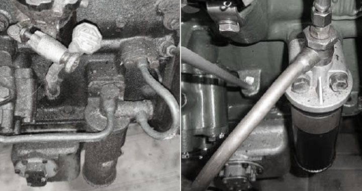
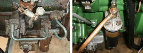
NOTE: If a replacement engine has been fitted the TPBG number may have been replaced with a Morris Motors Replacement Engines plate. - Oil Filter position on block. The Wet Clutch oil filter has two pipe connections, the Dry Clutch oil filter has only one connection and connects directly into the internal oilway in the block.

Picture b – Wet clutch & Dry clutch
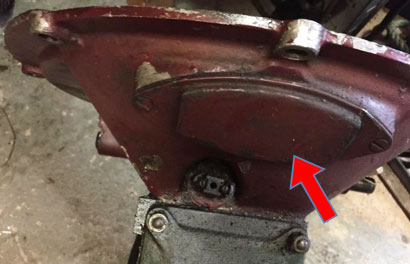
- Dry clutch engines have a timing inspection cover in the top of the clutch bell housing.
Picture c – Timing inspection cover
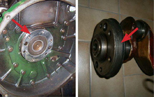
- The Crankshaft on the Dry Clutch engines are fitted with an oil return scroll whilst the Wet Clutch engines have no scroll.
Picture d – Wet clutch & Dry clutch
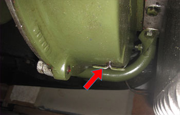
- Dry clutch engines have an oil leakage tell-tail hole with a loose split pin at the bottom of the clutch bell hosing.
Picture e – Hole in clutch bell hosing
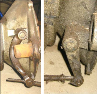
- The clutch operating leavers are a different shape. The Wet Clutch has a curved lever, the Dry Clutch has a straight lever.
Picture f – Wet clutch & Dry clutch
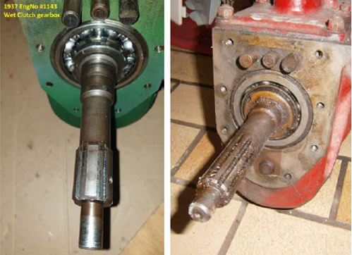
- The gearbox input shaft have a different number of splines. The Wet Clutch has 6 splines, the Dry Clutch has 10 Splines, and has a different shaft design.
Picture g – Wet clutch & Dry clutch
Part 2
Individual Component Identification
All the items listed below have been identified as either for a Wet Clutch power unit (ceased at TPBG 1509) or Dry Clutch power unit (commenced TPBG 1510) and are not interchangeable. Part Numbers are taken from the Revised 1946 Factory Service Parts List.
| Part Number | Part Description | Picture |
|---|---|---|
| Engine | ||
| MG795/10 | Engine Block | Figure 2 |
| S117/4 | Breather Pipe (Wet Clutch) | |
| S117/3 | Breather Pipe (Dry Clutch) | |
| MG735/107 | Bell Housing (Wet Clutch) | Figure 2 |
| MG795/102 | Bell Housing (Dry Clutch) | Picture ‘e’ above |
| MG795/104 | Split Pin (Dry Clutch) | |
| MG735/278 | Crankshaft (Wet Clutch) | Figure 2 |
| MG795/105 | Crankshaft (Dry Clutch) | |
| MG735/4 | Flywheel with clutch driving pins and crankshaft dowels (Wet Clutch) | Figure 2 |
| MG679/148 | Clutch driving pins (Wet Clutch) | |
| X679/14 | Dowel for crankshaft (Wet Clutch) | |
| MG795/26 | Flywheel (with dowels) for crankshaft and clutch cover (Dry Clutch) | |
| MG795/140 | Dowel for clutch cover (Dry Clutch) | |
| MG795/111 | Dowel for crankshaft (Dry Clutch) | |
| MG795/28 | Oil thrower for crankshaft (rear) (Dry Clutch) | |
| X679/15 | Spigot bearing for gearbox first motion shaft (Wet Clutch) | |
| MG679/57 | Centre for first motion shaft spigot bearing (with pins) (Wet Clutch) | |
| MG679/151 | Retaining plate for spigot bearing (Wet Clutch) | |
| X679/16 | Circlip for spigot bearing (Wet Clutch) | |
| P151/409 | Spigot bearing for gearbox first motion shaft (Dry Clutch) | |
| MG795/113 | Retaining plate for spigot bearing (Dry Clutch) | |
| MG679/152 | Bolt for securing flywheel (Wet Clutch) | |
| MG795/234 | Bolt for securing flywheel (Dry Clutch) | |
| MG679/153 | Spring for spigot bearing centre (Wet Clutch) | |
| X679/18 | Circlip for spigot bearing (Wet Clutch) | |
| MG735/12 | Cylinder head cover assembly (Wet Clutch) | |
| MG795/6 | Cylinder head cover assembly (Dry Clutch) | |
| A1034 | Air Cleaner (Wet Clutch) | |
| A1101 | Air Cleaner (Dry Clutch) | |
| MG795/133 | Rubber ferrule for air cleaner (Dry Clutch) | |
| A1017 | Starter motor (Wet Clutch) | |
| A1103 | Starter motor (Dry Clutch) | |
| A1017/2 | Starter drive end bracket (with bush) (Wet Clutch) | |
| A1103/1 | Starter drive end bracket (with bush) (Dry Clutch) | |
| A1107/6 | Starter Field coils (Wet Clutch) | |
| A1103/2 | Starter Field coils (Dry Clutch) | |
| MG735/19 | Oil pipe –pump to filter (Wet Clutch) | |
| MG795/7 | Oil pipe –pump to filter (Dry Clutch) | |
| MG706/410 | Joint for Oil Filter (Dry Clutch) | |
| MG706/426 | Bolt for oil filter (Dry Clutch) | |
| X151/15 | Spring washer oil filter bolt (Dry Clutch) | |
| MG735/20 | Oil pipe filter to block (Wet Clutch) | |
| MG679/249 | Joint for elbow (Wet Clutch) | |
| X679/61 | Bolt for oil pipe (filter to block) (Wet Clutch) | |
| Clutch | ||
| MG679/25 | Clutch Cover plate with gauzes, thimbles, and springs. (Wet Clutch) | |
| MG679/312 | Thimbles for Clutch springs (Wet Clutch) | |
| X679/51 | Screw for securing clutch cover (Wet Clutch) | |
| X151/15 | Spring washer for securing clutch cover (Wet Clutch) | |
| MG679/48 | Clutch pressure plate assembly (Wet Clutch) | Figure 4 |
| MG679/315 | Clutch spring (Wet Clutch) | Figure 4 |
| MG679/316 | Stop washer for clutch cover (Wet Clutch) | |
| MG679/317 | Clutch thrust race (Wet Clutch) | Figure 4 |
| X679/53 | Nut for thrust race (Wet Clutch) | Figure 4 |
| MG735/25 | Clutch driven plate assembly with corks. (Wet Clutch) | Figure 4 |
| X151/40 | Cork inserts for clutch driven plate (Wet Clutch) | |
| MG735/162 | Clutch withdrawal shaft O/S (Wet Clutch) | Figure 4 |
| MG679/322 | Clutch withdrawal shaft N/S (Wet Clutch) | Figure 4 |
| MG679/323 | Clutch fork (Wet Clutch) | Figure 4 |
| X679/55 | Key for clutch fork (Wet Clutch) | |
| X679/56 | Screw for clutch fork (Wet Clutch) | |
| MG735/163 | Clutch operating lever (Wet Clutch) | Figure 4 and Picture ‘f’ above |
| P151/8 | Key for clutch operating lever (Wet Clutch) | |
| X151/25 | Taper Pin for clutch operating lever (Wet Clutch) | |
| MG795/149 | Clutch Cover (Dry Clutch) | Figure 5 |
| MG795/150 | Clutch release lever (Dry Clutch) | Figure 5 |
| MG795/151 | Eyebolt for clutch release lever (Dry Clutch) | Figure 5 |
| MG795/152 | Nut for clutch release lever (Dry Clutch) | Figure 5 |
| MG795/154 | Fulcrum pin for release lever (Dry Clutch) | Figure 5 |
| MG795/155 | Strut for release lever (Dry Clutch) | |
| MG795/156 | Anti-rattle spring for release lever (Dry Clutch) | Figure 5 |
| MG795/157 | Retaining spring for release lever (Dry Clutch) | Figure 5 |
| MG795/158 | Release lever plate (Dry Clutch) | Figure 5 |
| MG795/14 | Clutch release bearing and cup assembly (Dry Clutch) | Figure 5 |
| MG795/161 | Retainer for release bearing (Dry Clutch) | Figure 5 |
| MG795/162 | Clutch springs (Dry Clutch) | Figure 5 |
| MG795/163 | Clutch pressure plate (Dry Clutch) | Figure 5 |
| MG795/15 | Clutch driven plate assembly (Dry Clutch) | Figure 5 |
| MG795/173 | Facing for clutch driven plate (Dry Clutch) | Figure 5 |
| MG795/174 | Rivets for clutch driven plate (Dry Clutch) | |
| X151/19 | Bolt for clutch cover (Dry Clutch) | |
| X151/15 | Spring washer for clutch cover (Dry Clutch) | |
| MG795/144 | Clutch withdrawal shaft (Dry Clutch) | Figure 5 |
| MG795/145 | Circlip for clutch withdrawal shaft (Dry Clutch) | |
| MG795/146 | Clutch Fork (Dry Clutch) | Figure 5 |
| X151/8 | Key for clutch fork (Dry Clutch) | |
| X706/4 | Taper pin for clutch fork (Dry Clutch) | |
| MG795/147 | Clutch operating lever (Dry Clutch) | Figure 5 and Picture ‘f’ above |
| P151/8 | Key for clutch operating lever (Dry Clutch) | |
| X151/25 | Taper pin for clutch operating lever (Dry Clutch) | |
| S64/10 | Clutch operating rod (Wet Clutch) | Figure 4 |
| S64/12 | Clutch operating rod (Dry Clutch) | |
| Gearbox | ||
| MG735/26 | Gearbox assembly (Wet Clutch) | Picture ‘g’ above |
| MG795/8 | Gearbox assembly (Dry Clutch) | Picture ‘g’ above |
| MG735/164 | Clutch housing (Wet Clutch) | |
| X679/63 | Core plug for clutch housing (Wet Clutch) | |
| MG735/165 | Joint for clutch housing (Wet Clutch) | |
| MG795/12 | Clutch housing with bushes and TDC indicator (Dry Clutch) | Picture ‘c’ above |
| MG795/141 | Bush for clutch operating shaft (Dry Clutch) | |
| MG795/142 | TDC indicator (Dry Clutch) | |
| MG795/143 | Rivet for TDC indicator (Dry Clutch) | |
| MG795/148 | Clutch inspection cover (Dry Clutch) | |
| MG706/270 | Screw for clutch inspection cover (Dry Clutch) | |
| MG735/168 | First motion shaft (Wet Clutch) | Figure 3 |
| MG795/122 | First motion shaft (Dry Clutch) | |
| MG735/175 | Mainshaft (Wet Clutch) | Figure 3 |
| MG795/189 | Mainshaft (Dry Clutch) | |
| MG735/176 | Front spigot bearing for mainshaft (Wet Clutch) | Figure 3 |
| MG827/353 | Front spigot bearing for mainshaft (Dry Clutch) | |
| MG735/220 | Selector shaft (reverse) (Wet Clutch) | Figure 3 |
| MG795/128 | Selector shaft (reverse) (Dry Clutch) | |
| MG735/221 | Gear Selector (reverse) (Wet Clutch) | Figure 3 |
| MG795/129 | Gear Selector (reverse) (Dry Clutch) | |
| MG795/130 | Plunger for gear selector (Dry Clutch) | |
| MG679/395 | Spring for gear selector (Dry Clutch) | |
| MG679/396 | Ball for reverse plunger (Dry Clutch) | |
| MG679/397 | Spring for reverse plunger (Dry Clutch) | |
Starter Motor
The starter motors are not interchangeable as they have different mounting flanges. The Wet Clutch starter motor has a three bolt fixing with the bolts equally spaced at 120 degrees. The Dry Clutch starter motor is also a three bolt fixing with two of the bolts diametrically opposite each other and the third bolt at 90 degrees to the other two.
Additional changes to power unit
The document covers the major changes on the change to a dry clutch at engine number TPBG 1510, further changes to the power unit occurred at:
- TPBG 1254 Engine front steady rubber (replaces tie straps).
- TPBG 1770 Bolt for oil filter banjo and washers.
- TPBG 1790 Sump changed. (Illustration No.1)
- TPBG 1891 Counterbalanced crankshaft installed.
- TPBG 1891 Oil suction pipe changed.
- TPBG 1891 Gearbox mainshaft.
- TPBG 1891 Gearbox front spigot bearing.
- TPBG 1891 Gearbox sliding hub with synchronizing cones.
- TPBG 1891 Gearbox spring for mainshaft striking dog.
- TPBG 1891 Gearbox mainshaft 3rd speed gear, rollers, and locking plate.
- TPBG 2100 Oil feed pipe to cylinder head.
- TPBG 2237 Gearbox striking dog (top and third).
- TPBG 2237 Gearbox mainshaft 1st speed gear.
- TPBG 2237 Gearbox ball for mainshaft.
- TPBG 2237 Gearbox selector fork (1st and 2nd).
- TPBG 2237 Gearbox selector shaft (3rd and top).
- TPBG 2237 Gearbox selector shaft (reverse).
- TPBG 2286 Piston Change.
- TPBG 2292 Piston Change.
- TPBG 2250 Support bracket for rocker shaft.
- TPBG 2511 Oil feed pipe to cylinder head.
- TPBG 2751 Top cap valve springs.
- TPBG 2731 Push rod change.
- TPBG 2822 Connecting rod change.
It can be seen from the list above the significant other changes to the power unit also occurred at engine TPBG 1891 and at TPBG 2237.
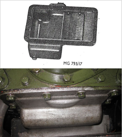
Figure 1 – Sump Dry Clutch Engine (From TPBG 1790)
NOTE: The counterbalanced crankshaft cannot be fitted to the early dry clutch power units (TPBG 1510 to TPBG 1890) without changing the sump (up to TPBG 1790) and changing the oil suction pipe as they foul the crankshaft and stop it rotating. The clutch housing also has to be machined out by approximately 1mm as the flange on the crankshaft is slightly larger.
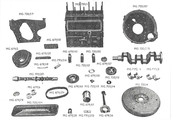
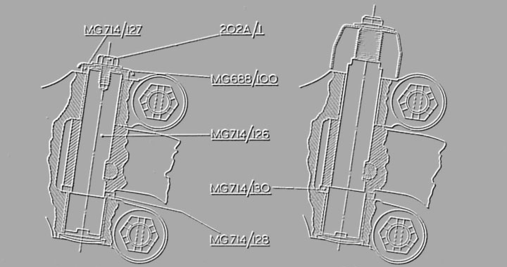
Figure 2 – Engine Components – Wet Clutch
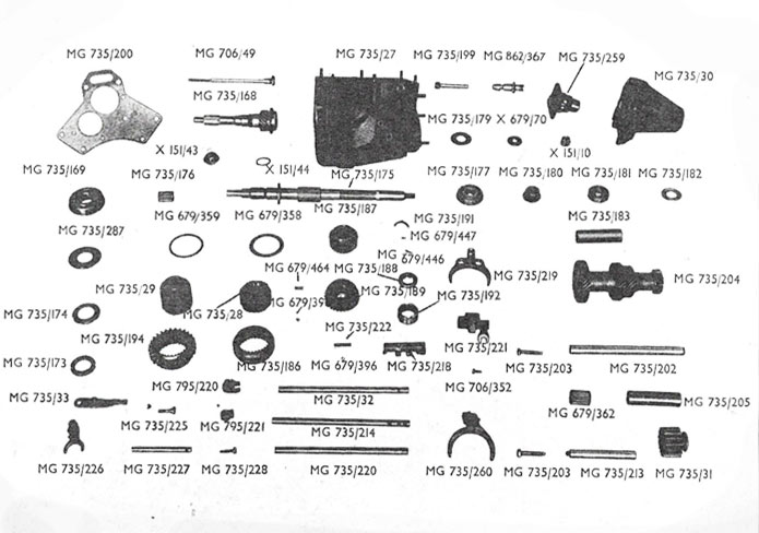
Figure 3 – Gearbox Wet Clutch Engine
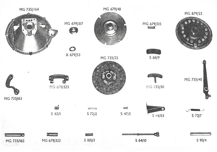
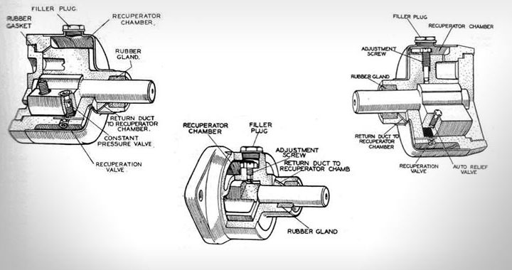
Figure 4 -Wet Clutch
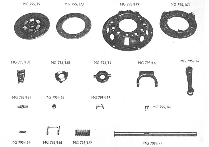
Figure 5 – Dry Clutch