by John Bannister
The Rocking & Rolling and Rocking & Rolling – Part 2 articles advised on ways to maintain and improve the road manners of our cars. This article continues with this theme, hopefully providing more useful advice on ways to improve the safety, road handling and the driveability of our cars. All three articles should be read in conjunction with each other before starting any maintenance checks or improvements, as they are closely interrelated. (These notes specifically refer to the MG VA, but they are also generally applicable to the SA & WA models and some other pre-war MG’s).
Castor Angle
Car Stability and Driving Dynamics are significantly affected by the Castor Angle geometry of the front beam axle. On VA Cars, the angle was pre-set at the MG Factory by means of two small steel wedges sandwiched between the underside of each front spring and the top face of the axle beam.
Over the intervening years, it is possible that these wedges have either been damaged, accidentally fitted back-to-front, or even left out altogether! The Castor Angle provides an automatic self-centering action to the steering, so it is very important that the wedges are fitted correctly.
Firstly, check that the thicker edge of each wedge is facing towards the rear of the car on both sides. Then check that both wedges are approximately the same thickness and that the central hole in each wedge is large enough to fit over the locating peg to allow secure assembly without damage.
Front Axle King Pin holes
Excessive rocking movement of either front wheel assembly will make handling dangerous and is a certain MOT failure! (Now that our cars are exempt from compulsory MOT checks, Insurers could possibly use this as an excuse not to pay out in the event of a claim, effectively rendering your policy invalid!) Evidence of sideways movement for a newly replaced pin in either King Pin hole in the front axle beam confirms that the hole is oval and must be repaired.
To avoid weakening the front axle beam, fitting bushes in King Pin holes was not previously recommended, however due to the difficulty of sourcing un-worn axle beams, and having checked that there appears to be sufficient material to insert a thin steel bush with a maximum wall thickness of 3mm, bushing is really the only option available now!
Both King Pin holes must be bored at the correct “negative” Camber Angle of 8 degrees to the vertical for our SVW cars and the new bushes pressed in as a light interference fit. Replacement King Pin sets can then be fitted into the new bushes.
Cracked axle hub-shafts
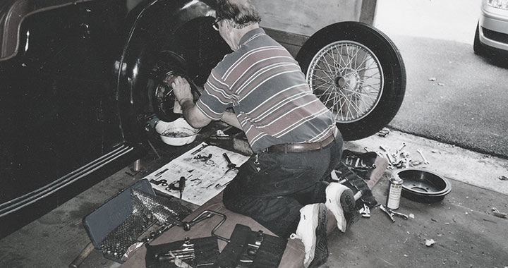
Annual inspection of the wheel Hub-Shaft Splines on our 75-year old cars is essential to avoid potential catastrophic failure! Remove all 4 wheels, use solvent to clean grease away from the Hub Spline and visually check for cracks!
Over time, circumferential cracks can occur due to repeated hammering and excess tightening of the wheel spinners by over-enthusiastic owners. This stretches the work-hardened Hub Splines beyond their yield-strength and dangerous cracks can develop. Eventually these cracks will spread right through the hub and a wheel will just snap off without warning!
Unfortunately, this is most likely to occur during high-stress conditions, such as severe cornering or braking! Either of which could lead to very serious consequences!
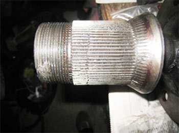
Cracked axle hub-shafts
Look for circumferential cracks about 1/3 way along the hub-shaft spline as in the photo.
If cracks are evident, the only remedy is to replace the axle stub shafts with new ones. It is also advisable at the same time to fit new wheel bearings, new rear half-shafts (hydraulically pressed into the new rear hubs) and new oil seals. Always re-grease the outside of new hub splines to ensure ease of wheel-removal later! If the mating wheel hub spline serrations are also worn, then it is advisable to have the hubs replaced too and the wheels rebuilt with new spokes!
On my 1938 VA, ALL four wheels hubs had serious cracks which were already 1/3 through the hub thickness!
So, please Be Warned and check your splines NOW!
(Note; To prevent Differential oil seeping past the half-shaft/rear wheel hub interference, which will stain the wheel rims and rot the tyre wall, push an oil-absorbing rag firmly into the hub recess hole before fitting the Wheel Spinner).
Leaf Springs
Modern cars usually have independent coil-spring suspension all round and use unequal wishbone geometry to give exceptional road handling. Unfortunately, the old-fashioned Leaf Spring design for our SVW cars is crude and simply replicates the ancient design used on slow moving horse-drawn carriages and farm wagons! These springs are basically curved strips of flat toughened steel, clipped together into sufficiently strong bundles to handle the load.
A major failing of this design is that the apparent length of a curved leaf spring grows as it flattens with increasing load, but only up until the point where the leaves are completely flat after which the apparent length starts to decrease again. To accommodate this change in length, leaf springs are fixed directly to the car chassis at one end only and the change in spring length is accommodated by means of swinging Shackles at the other end.
When cornering, the car body rolls outwards towards the bend thereby loading up the leaf springs on that side. Both outside springs flatten and lengthen and this causes the front and rear axles to move apart on that side by up to 1/2 inch! The opposite happens to the inside springs which become less loaded and these shorten by up to 1/2 inch.
The unwanted consequence of this is that instead of the front and rear axles staying parallel to each other, they actually turn in and “self-steer” by a combined total of up to 1 inch depending how much the body rolls!
This effectively (and quite suddenly) steers the car more sharply than the driver expects! This is called “over-steer” and can take an unsuspecting driver by surprise! Fortunately this somewhat erratic handling characteristic can eventually be mastered once the driver has become more accustomed and experienced in driving older cars!
Unfortunately, stability is made much worse if the springs have lost some of their curvature or strength with age, and especially when the car is heavily loaded or is cornering very fast. This is because any further excessive body roll will take the springs past the mid-point and they will effectively start to shorten again! This suddenly and spontaneously, transforms the over-steer to under-steer (usually on the rear axle first), without any further input from the steering wheel, and the car then requires speedy opposite-lock correction by the driver to stay in control!
Most of us may possibly have experienced that somewhat frightening situation at some time! A similar situation will also be apparent if the car is inadvertently driven over a bump or into a pothole! The axle steering direction will be changed by the sudden spring flexure on one wheel and the car will steer away from the driver’s anticipated direction!
This old suspension design is fundamentally flawed, however “driveability” can be improved significantly if the curvature of “sagging” springs is corrected back to the “as-new” shape. (Fitting anti-roll bars is also a good solution).
“Blower’s” MG Workshop Manual shows the “as new” leaf-spring dimensions for our cars on Pages 495-6 (504-5 on my copy-Ed.). These are also shown at the end of this article.
It is worth comparing your unloaded springs with these original dimensions to see if they need re-setting. A quick way to check the springs is to load up your car with four heavy adults and look to see if the springs are still curved the correct way. If they are flat, or curving downwards at their ends, then they need removing, re-shaping and possibly re-tempering as well. The car will have to be fully supported under the chassis to allow all four Leaf Spring bundles to be removed and only specialist companies should be approached to re-shape and re-temper the individual leaves. Brost Forge, who advertise in the Review, are one of the very few companies still offering this service.
Leaf Spring Shackles
Worn shackles at the floating end of the leaf springs can also contribute significantly to unstable handling problems.
Check that the “pivot” assemblies on all four leaf spring mountings are not worn. The rear of the front springs are connected onto the chassis by a hardened pin and bush assembly, and the front of the rear springs use a pin and rubber Metalastic bush, (Very modern technology for a pre-war car!) whilst the opposite ends of these springs are located between swinging Shackle Plates.
The main wear points are the holes in the hardened shackle side plates and shackle pins themselves at the “moving” ends of the leaf springs. Each shackle pin usually has a small dowel peg which is designed to fit into a slot in the shackle plate to prevent rotation and minimise wear. Often these “soft” dowels shear with age, or over-tightening of the Shackle Bolts, allowing the pin to rotate in the shackle plate. Both parts then wear rapidly and the car body is no longer securely held to the suspension! (To avoid the possibility of the soft pin shearing, it is best to replace each of the soft mild steel dowel pins with a hardened drill bit of the same diameter, ground off to the correct length).
It is also recommended that the shared lower grease feed pipe to each rear spring shackle is replaced with a single local grease nipple and the pipework modified so the grease feed pipe feeds the top rear shackle only (the dual-feed grease lubrication system seldom works due to one side becoming blocked with thick grease, leading to grease starvation and premature wear at this connection!).
Correct assembly of the Shackles and spacing bushes is important as Shackles rely on the protruding metal rubbing-plate block to provide side-ways rigidity to the rear axle. The Bronze wear Washers must NOT be positioned on the “inside” of these plates, but should be fitted on the outside of the shackle plates only! Shackle bolts should be just tight enough to take up any clearance whilst still allowing the shackles enough freedom to pivot.
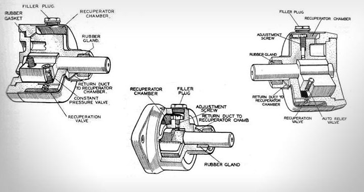
Steering Box Rebuild
The design of the Bishops Cam steering box recognises that most wear will take place over the central portion of the hardened worm inside the box, as this is the section in constant use under normal “straight ahead” driving. Shims can be removed from under the Steering Box side plate to compensate for any Cam or Steering Pin wear.
Extra internal clearance is specifically provided towards both ends of the steering box worm to allow this adjustment to be made without causing the steering to tighten on full lock. (This is permissible because slack steering at full lock is perfectly acceptable at low speed). However, problems do eventually arise when the central section becomes more badly worn than the original clearance provided at the ends of the worm. This then causes a correctly adjusted steering box in the “straight-ahead” position to become tight (or even seize up completely) on full lock! Radiated heat from the exhaust onto the Steering Box can make this condition even worse, especially during long runs or hard driving!
The recommended way to correct this problem is to have the steering box rebuilt with a new worm and new hardened conical pin. Unfortunately, new steering box worms are very hard to source and it is impossible to re-grind a worn worm as these were fully machined before the hardening process, so nothing can be done to recover them afterwards.
There are two possible solutions to this type of serious steering box wear problem.
- Bert van der Linden, an SVW Member in Holland, has successfully used his modified design for the Bishops Cam end plate where small amounts of worm wear are automatically compensated for by means of spring-loaded internals.
- Provide the clearance needed by dismantling the steering box and locally grinding the equivalent clearance off the face of the hardened conical pin towards the ends of the steering stroke! (Not applicable to WA’s as the conical pin is free to rotate). It is very important that the “straight-ahead” Pin contact point is left un-ground. Grinding may require several attempts to check that there are no internal high spots remaining which would cause local steering box stiffness. This type of work is best left to a specialist machine shop.
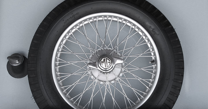
Knock-On Wire Wheels
Rudge-Whitworth wheels are fitted to our cars. These crucial items are often overlooked and taken for granted!
All spokes should be regularly checked, especially after a long drive. They should all “ping” with a similar tone when tapped with a metal object such as a screw-driver. Any dull-sounding, loose or sheared spokes must be tightened or replaced immediately, and especially any spokes with brown rust staining at the wheel rim which indicates a loose or broken spoke end.
One failed spoke often leads to others breaking nearby on the same wheel due to the extra load these then have to carry, so this can soon become a very serious matter! Loose or damaged spokes are an MOT failure item too!
At any one time, the whole weight of your car is actually “hanging” on only about 4 spokes per wheel, plus there are the extra cornering and braking forces as well, so it is amazing that these wheels are so reliable! But they do also need regular inspection!
Spokes usually come in two lengths depending whether they fit on the inside or outside of the wheel rim. The tyre and inner tube must be removed and then it is a simple matter to refit a new spoke. It is very important that the protective canvas or rubber strip is correctly re-fitted over the ends of the spokes to prevent these damaging the tube.
When replacing a spoke, only tighten it sufficiently to allow it to give the same ping as the adjacent spokes. Over-tightening can over-stress the spoke and can also cause the wheel rim to distort. All 5 wheels should be checked for “trueness”. To do this, jack each wheel off the ground in turn and spin the road wheel manually. The gap between the tyre face and the floor should be constant within approx 3-5mm maximum. (Allow for the fact that there may still be a flat spot on the tyre from where it was standing).
The face of the wheel rim should run “true” as well. This can be checked by holding a large block of wood, or similar object near to the edge of the wheel-rim face and measuring any difference in the gap when each wheel is spun a complete revolution. Again, only a small variation of approx 3-5mm can be tolerated. (The spare wheel can be checked in a similar way by fitting it temporarily to one of the axles). If you need further help or advice, specialist
wheel repairers and manufactures advertise in the Review.
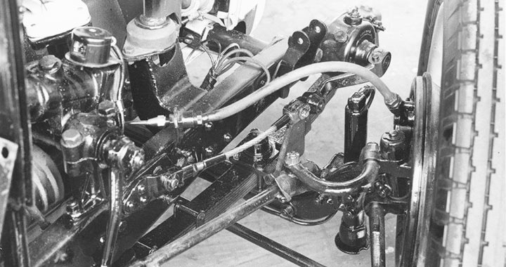
Telescopic Shock Absorbers
The “Lever or Vane-Type” oil-filled shock absorbers originally fitted on our cars will often no longer be effective, due to internal wear allowing the hydraulic oil to leak out! Costly refurbishment is possible for the purists, but an alternative is to fit modern telescopic shock absorbers instead. Fitting these does not require any drilling or modifications to the chassis as they fit directly onto the same holding bolt holes, and the original units can always be retro-fitted again at any time if desired!
SVW Spares Ltd, who advertise in the Review, sell a kit for all SWV cars which consists of the correct spacers, brackets and modern shock absorbers. (Some owners have bought the spacers and brackets only and then purchased their own choice of telescopic shock absorber). Road handling and ride is very much improved, so this modification is well worth doing.
Brake Fluid
There are two main types of Brake Fluid.
- Glycol-Ether Brake Fluid is the one most commonly available. It costs around £10 per litre and is sold in various qualities from DOT 2 to DOT 5. The higher the DOT number the higher the potential boiling point specifically for high-performance cars. Glycol-Ether fluid is toxic, will damage car paint if not immediately wiped off, is combustible and absorbs water over a few years which lowers the boiling point, but more importantly for our cars this absorbed moisture can also cause the brake cylinders to rust internally and seize up whilst the cars are standing over winter.
- Silicone Fluid is approximately 4 times as expensive, will not damage paintwork, and does not absorb water. It can however be totally incompatible with the rubber used to make brake cylinder seals. As a consequence, any new rubber seals must first be soaked in Silicon fluid for several days, and preferably for much longer, to check that the rubber does not weaken and swell up under constant contact with this fluid! The whole brake system must also be flushed out completely and fully purged with a solvent such as Methylated Spirit and then completely dried out with compressed air blown through the brake pipework to ensure all traces of the previous Glycol-Ethyl fluid are removed! This is a tedious job. Once filled up again, only Silicone Fluid can then be used for topping up!
For our low-performance cars, the best option is to use the standard Glycol-Ether DOT3 or DOT4 Brake Fluid in preference to Silicon Fluid. It is important to flush the system thoroughly at least every 5 years anyway to avoid brake cylinder corrosion or seizure from moisture absorption. This type of brake fluid is also the preferred choice of most modern family car manufacturers.
Summary
Whilst driveability in a 75 year SVW car can never be directly compared to modern standards, our cars are still good fun on the open road today. This is especially true if all the potential faults mentioned in the three Rocking & Rolling Articles have been checked and corrected where necessary!
Hopefully these notes will give owners a better insight into what to look for and an opportunity to correct any faults on their cars and you will have many more years of enjoyable, safe driving!