Luvax Vane or Rotor Type of Hydraulic Shock Absorbers, which were fitted as standard equipment on a number of British cars prior to 1939, are of three types:
- The Constant Pressure Non-Adjustable Type
- The Adjustable Type
- The Finger-Tip Control Type
Certain instructions issued by the makers of these shock absorbers are common to all three types. These are as follows:
Refilling with Fluid
After about every 5,000¬8,000 miles running, unscrew the filler plug and if necessary top up to about 3/4″ BELOW THE FILLER PLUG. It is most important to leave ail air space in the top of the chamber for the expansion of the fluid. Where it is not possible to see inside the filler plug hole, fill the shock absorber, then withdraw a small quantity of fluid by means of a syringe.
Luvax Shock Absorber Fluids
Three different fluids have been used by the makers in the Luvax Vane or Rotor Type of Shock Absorber.
Fluid No. 1:
This fluid was a combination of fish and grape seed oils; it had a golden brown colour and was in use on all “Home” models of Luvax up till 1936.
Fluid No. 2:
This is a mineral oil having a greenish-red colour; it superseded Fluid No. 1 and is still the correct type of fluid to use on all Vane or Rotor Type Absorbers. This fluid will not mix with Fluid No. 1 and it is essential that all units are thoroughly dismantled and cleaned before using this fluid.
Luvax Export Fluid No. 3 for Extremes of Climate:
It will be readily understood that excessive variations in temperature have an effect on the efficiency of shock absorbers due to the changes which take place in the viscosity of the fluid employed.
The effect of this variation is to increase or reduce resistance to spring movement when applied to a car and it will be clear that some adjustment is necessary to obtain the maximum efficiency. As a result of experience and laboratory tests a fluid has been compounded which will operate satisfactorily at temperatures as low as 30° F. and which is also satisfactory at the opposite end of the scale. This fluid is known as Luvax Export Fluid No. 3 and possesses a glycerin base with additions of dextrin and alcohol.
It should be made quite clear that Export Fluid No. 3 will not mix with either of Fluids No. 1 or No. 2 and to obtain the maximum results it should not be used with any other fluid.
In order to identify shock absorbers filled with Export Fluid a round metal tally bearing the word “Export” was attached to the filler plug but this was later superseded by a filler plug having a conical or domed top.
Where it is desired to use the Export Fluid it is necessary to remove all traces of the original fluid by washing out with petrol, this being possible after removing the regulating screw and pumping the lever arm with shock absorber inverted, or better still, the work should be done in a workshop where competent fitters can remove the back plate of the shock absorber, and wash the whole of the working parts in petrol ; care being taken to mark the cover when unscrewing, and to see that it is screwed up to the same point when refitting.
As this fluid has an entirely different viscosity from the other fluids, when it is used it will be necessary to re-time the shock absorbers to the correct settings. The method used for re-timing is described on pp. 132 to 134.
Even with this fluid it will still be necessary to make adjustments when used under severe conditions and these may be effected by means of the screw situated underneath the filler cap until the required degree of damping is obtained. The resistance may be increased by turning the screw in a clockwise direction or decreased by turning in an anti-clockwise direction. The necessity of avoiding too great a resistance to spring movement must be emphasized, for besides giving a most unsatisfactory ride, an added strain is thrown on the shock absorber itself, fixing brackets, chassis frame, etc. This point cannot be too strongly stressed as oversetting will certainly cause serious internal damage, and half-turn of the adjusting screw should provide the adjustment necessary for all but the most abnormal conditions.
If it is necessary to adjust to this extent, it is desirable to feel the resistance with the linkage disconnected, before allowing the vehicle to go into service.
The foregoing information should assist servicemen in dealing with any instances of difficulty. Particularly where considerable variation between winter and summer temperatures exists, it being understood that a fall in temperature increases the resistance to spring movement and the reverse when the temperature rises again.
All the above types of fluid can be obtained in pint tins from. Any Lucas agent in Australia or New Zealand. One-gallon tins are also available for garage and service station use.
General Servicing Instructions
When a complaint is received that riding of the car is not satisfactory, do not jump to the conclusion that the shock absorbers require attention. It will be appreciated that these units are only part of the car’s suspension, and it should be ascertained from the driver the type of riding that is being obtained from the vehicle, namely, is the riding too hard, or is it too soft 2 When this has been found out, check over the tyre pressures, then examine the springs to see that they are not rusted up. If the springs are a type which should be lubricated, see that they are not too dry. If they are a design which relies on inter-leaf friction, make sure they are not lubricated. Examine also the spring clamps, and the shackle bolts, making sure that they are all correct. If nothing is found amiss in any of these directions, then examine the shock absorbers, by first ascertaining that they are firmly bolted to the chassis.
Failure to top up regularly is one of the main causes of shock absorbers losing their resistance. It should be pointed out, however, that providing the shock absorbers have not been subjected to overloading due to a faulty spring, it is very unlikely that poor riding can be attributed to the shock absorbers.
1. Constant Pressure Non-adjustable Type
This type of Luvax Shock Absorber which is shown in Fig. 1 is designed so that adjustment in service is unnecessary.
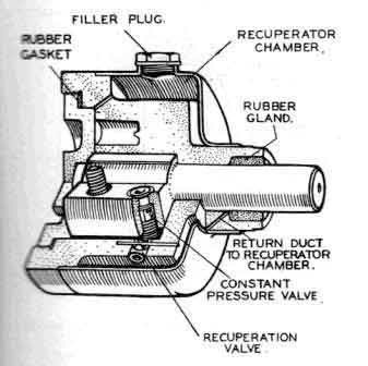
Fig.1. CONSTANT PRESSURE TYPE SHOCK ABSORBER
This type of Luvax shock absorber is non-adjustable.
The valve in this type of shock absorber is of the spring loader variety and is carefully set by the makers before leaving the factory. As it is not provided with adjustment it should be returned to the makers or to one of their Service agents for regulation should this be required.
Emptying the Unit:
If for any reason it is necessary to empty the unit the back of the shock absorber must be removed by means of the special tool illustrated in Fig. 2.
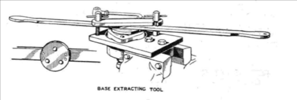
Fig.2. BASE EXTRACTING TOOL USED FOR REMOVING THE BACK OF THE SHOCK ABSORBER PREVIOUS TO REFILLING.
The unit can then be cleaned out, refilled and the back replaced. Care must be taken to ensure that the rubber gland between the back plate and its location is in good condition, and sealed with “Hermetite” or similar compound.
Servicing:
The general servicing instructions given above apply to this type of shock absorber. After having examined the spring, the spring clamps, shackle bolts etc., and after having ascertained that the shock absorbers are firmly bolted to the chassis, remove the connecting link and by feeling at the rotor arm see if there is any resistance. If no resistance is felt then the units should be returned to the nearest Luvax Service Station for attention.
Later Refinements:
As an added refinement and to meet the special needs of the motor trade, where unusual conditions of service prevail, the makers some time ago decided to incorporate an adjustment screw to this type (non-adjustable) of shock absorber.
The adjustment can be carried out in just the same manner as for the standard type of shock absorber, namely by removing the filler cap and turning the square-headed screw clockwise or anticlockwise as desired.
2. Adjustable Types
Two adjustable types of Luvax Hydraulic Shock Absorbers are shown in Figs. 3 and 4 respectively.
Adjustment:
The adjustment of the shock absorber is made by means of the screw which is accessible when the filler plug in the top of the shock absorber is removed.
If it is desired to increase the damping of the road springs by tightening the shock absorber, the regulator screw which is locked by a spring should be turned to the right thus closing a valve in the `reacting block of the shock absorber. To decrease the amount of damping turn the screw to the left, thus opening the valve and permitting a more free flow of fluid. This enables a fine degree of adjustment to be obtained and it is sufficient to turn the screw a quarter of a turn at a time and ascertain by road tests if the necessary adjustment has been made.
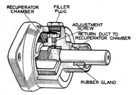
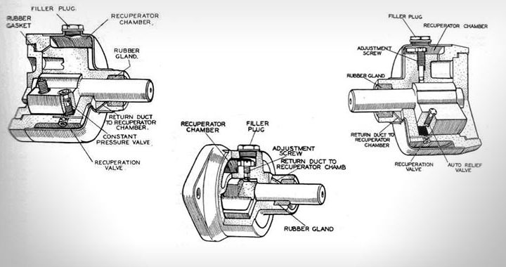
Fig.3. SECTIONAL SKETCH OF THE R.A. TYPE OF LUVAX
If the original setting of the shock absorbers is lost, then by disconnecting the bottom end of the connecting link and moving the lever by hand, the four shock absorbers can be balanced by hand.
Loss of Resistance:
If the performance of the shock absorbers is not restored by adjustment, remove the connecting link and by feeling at the rotor arm, find out if there is any resistance. If the arm moves with practically no resistance over a portion of its travel, this is probably due to the presence of air as well as fluid in the working chamber. If the air has been present for some time, this will have become thoroughly mixed with the fluid, which will then be in a frothy state.
After a little experience, the existence of frothy fluid can be felt by the springy feel of the lever arras but it is wiser to examine the fluid in the working chamber as follows:
Remove the adjusting screw and slowly move the shock absorber arm. This will force a sample of the fluid out of the chamber and if this appears to be frothy and aerated the working chamber must be completely emptied by removing the shock absorber and turning it so that the fluid filling orifice points downwards and then moving the arm to completely empty the working chamber.
Finally flush out the shock absorber with petrol.
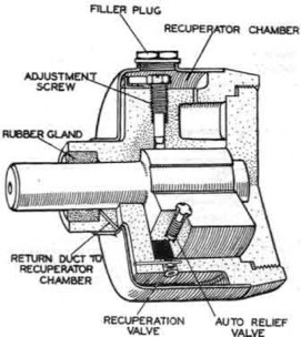
Fig.4. SECTIONAL SKETCH OF THE A & B TYPES OF LUVAX SHOCK ABSORBERS
After the petrol has been allowed to evaporate, the shock absorber must be refilled with fluid. Force into the working chamber as much Luvax Shock Absorber Fluid as possible, by means of syringe through the adjusting screw hole. Replace the adjusting screw. To complete the operation fluid must be poured into the supply chamber and the rotor arm moved backwards and forwards until all free movement of the rotor arm has disappeared. While doing this the rotor arm must not be forced beyond the point where fluid resistance is felt as this will tend to cause aeration again. The recuperator chamber must be filled with fluid to level just below the filler plug.
Finally the shock absorbers must be adjusted a previously described.
The general instructions for servicing and re filling with fluid, previously given, are of course applicable to this model.
3. The Finger-Tip Control Type
These shock absorbers are arranged to be self-adjusting, the amount of damping being dependent on the movement of the car axle. In addition, a finger-tip control is provided to alter the adjustment according to the load, personal taste, etc.
The system consists of valves in the shock absorbers which are operated by fluid pressure, the source of pressure being a pump, operated by one of the shock absorbers. This pump will generate pressure in proportion to axle movement: the more the axle bounces in relation to the frame, the higher the pressure generated in the system, and the further the shock absorber valve will be closed, thus increasing the clamping capacity. Conversely, when the relative movement between axle and frame decreases, the pressure will be decreased, the shock absorber valve will be opened, and the damping capacity reduced. It thus provides an automatic control for the damping of the road spring.
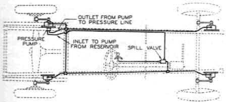
Fig.5. HOW FINGER TIP CONTROL LUVAX SHOCK ABSORBER IS OPERATED
The over-riding control is provided by a spill calve, which enables the pressure generated by the shock absorber pump to be discharged into a reservoir at varying rates, depending on the position of the spill valve, which has five positions giving a graduated rate of discharge into the reservoir (which is at atmospheric pressure) . From the bottom of this reservoir the oil is sucked back into the pump on the shock absorber. Usually the mid-position will be the, best place for the control lever, as rough roads will automatically increase the damping, and smooth roads reduce it, but if, due to increase of load or increase of speed, a fiercer damping is required, then the valve will be shut. If, on the other hand, the load was small, and it was desired to have maximum flexibility, then the valve would be open. It will of course be realized that the automatic variation occurs in any position of the control valve lever, except that when the vale is fully open the damping will not be decreased by a smoother road, but will be increased by a rougher road. These conditions are what are required to attain the best results.
Maintenance:
This type of shock absorber is culled with fluid as described above.
If for any reason it is necessary to empty the unit, the back of the shock absorber must be removed by means of the special tool shown in Fig. 2. The unit can then be cleaned out, refilled and the back replaced. Care must be talc en to ensure that the rubber gasket between the hack plate and its location is in good condition.
Control System:
Occasionally examine the fluid in the spill valve reservoir. If necessary, add a thin oil, such as Mobil oil Arctic, to bring the level to within one inch of the top. Shock Absorber Fluid must not be used in the control system.
Servicing the Control System:
If, owing to a pipe line being disconnected or to any other reason, some of the fluid in the control system is lost, the pipe line must be refilled until it is completely full of oil. An oil gun, filled with the correct grade of oil, must be used. Disconnect the outlet pipe from the bottom of the spill valve reservoir and attach the oil gun to the pipe line. Disconnect the unions on top of all four shock absorbers, then force oil from the gun into the pipe line until the ends of all four pipes are flowing with air-free oil. Reconnect the ends of all four pipes to the shock absorbers and then with the spill valve in the closed position raise the pressure in the system, with the oil gun, until the relief valve opens and discharges oil into the spill valve reservoir. When the filler cap is removed oil may easily be seen surging past the cone valve.
Finally, with pressure maintained in the system as described above, the line should be carefully examined for leaks or weeping of oil at any joint. Every joint in this line must be oil tight and should there be the slightest crack in the pipe line a new length of pipe should be fitted. This pressure test is very important as under working conditions this pipe line is a suction line and the slightest tendency to suck air will prove fatal to the proper functioning of the system.
The car is now ready for service, and should be checked by running on the road to see that the desired control is obtained.
Varieties of Luvax Vane Type Shock Absorber:
With regard to the varieties of Luvax shock absorbers fitted to cars previous to 1939 the principal types are as follows:
- Type “A” Small pattern for light cars.
- Type “B” Medium pattern for medium power pleasure cars.
- Type “ALC” For light commercial and high power pleasure cars.
Variations of the “A” type shock absorber:
- “AC” Denoting that the “A” type shock absorber is fitted with a constant pressure valve. This type is so designed that adjustment in service is unnecessary.
- “AVG” This is similar to “AC” except that it has a vertical fixing.
- “AR1”, “AR2” etc. Denoting that the “A” type absorber is fitted with a relief valve in addition to the ordinary regulating valve.
- “AVR” Similar to “AR” type but has a vertical fixing.
- “ATR” Is fitted with a thermostatic relief valve in addition to the ordinary regulating valve.
- BC” “BR” “BTR” “BVR” are “B” type units with the same variations incorporated in them as are mentioned above for the “A” type.
Type “RA” shock absorber was a small unit having a cast iron or die-cast body incorporating the recuperation chamber, and without a detachable metal cover. This unit was fitted only to light pleasure cars and is now obsolete.
Lucas also make a special type of absorber having the flange next to the spindle. This is known as the “CMP” type. Other forms of “CMP” type are “CMPC”, “CMPR” and “CMPVC”, the letters C, R and VC indicating constant pressure, relief valve and constant pressure with vertical fixing respectively, similar to the description given above in the case of the “A” type.
During the 1937 season, Lucas changed from the cotter pin method of securing the lever arm to the shock absorber spindle, to a splined shaft fixing, where the arm is pressed on to the shock absorber spindle in a hydraulic press, and in order to distinguish this type of fixing, the symbol 5 was added to the shock absorber numbers. Thus, a shock absorber type “AR1” when fitted with a splined shaft became “AR51”.
Other Luvax shock absorbers are designated “RMP”, “RMPC “, “RIVLPR”, “RMPTR”. These are the “B” type units fitted with the splined shaft, or spindle. The letters “C”, “B” and “TB” have the same meaning as previously described.
When testing these “RMP” type of shock absorbers for timing, they are tested just as in the case of other “B” units, that is, with a 200 lb. in. torque (e.g. a 20 lb. weight at a distance of 10″). The “ALC” type shock absorbers are tested with 300 lb. in. torque (e.g. a 30 lb. weight at a distance of 10″).
Where numbers are attached to the shock absorbers, such as “AR1”, “AR-27 ” etc. these figures indicate that these types, whilst belonging to the “AR” type for instance, are distinct from the “AR” type itself, by having incorporated in the unit some special feature, probably to suit the car manufacturer, upon whose car they are fitted.
Where the letter “E” is incorporated into the designation of any shock absorber, it indicates that this is a special model for the export chassis of the car.
Timing Tests of Luvax Vane Type Shock Absorbers for Resistance
It is of course essential that shock absorbers on opposite sides of the car should have practically the same resistance; otherwise the riding of the car would be considerably affected. In other words, each of the front pair of absorbers must have the same resistance, and likewise each of the rear pair also, although the resistance of the front pair is scarcely ever the same as that of the rear pair. This resistance is measured by the time taken in seconds for the arm of the shock absorber when loaded with a certain weight hung at a prescribed distance from the centre of the spindle on which the arm is fixed, to move through an angle of 100 degrees. In the case of the smaller or “A” type of absorbers, the distance is 5″ and the weight 20 lb. so that the turning effect or torque for the “A” type is 20 x 5 or 100 in. lb. In the case of the larger or “B” type, the distance is 10″, the weight 20 lb. and the torque thus 20 x 10 or 200 in.lb.
Before each shock absorber leaves the factory it is tested and regulated to the predetermined resistance and timing, and the time taken for the arm to move through an arc of 100 degrees is recorded. This time is stamped on each Luvax shock absorber. In the case of the fairly recent pre-1939 (“P” type) models, the time in seconds is marked on the inside portion of the back of the shock absorber and in the case of the older type of cotter-pin fixed absorbers, on the end of the spindle.
The checking of the timing and thus of the resistance, of the Luvax absorbers can readily be undertaken by any garage man who cares to provide himself with the simple Timing Board and Timing Bars described and illustrated herewith.
Luvax Universal Timing Board
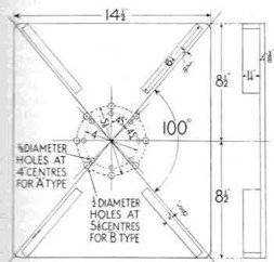
Fig.6. LUVAX SHOCK ABSORBER TIMING BOARD
The Luvax Shock Absorber Timing Board shown in Fig. 6 is made from a sheet of ⅜” thick mild steel, 14 ½” wide and 17″ deep. The general layout of the board can be readily understood from the diagram. If the board is made exactly the sizes shown, the diagonals will enclose an angle of 100 degrees. It will be noticed that the strips of hardwood are fastened parallel to the diagonals and in each case ³⁄₁₆” from them. As the timing bars are 1¼ ” wide, this ensures that the timing bar affixed to the absorber spindle actually traverses 100° when moving between the fixed blocks.
[Ed: Tangent 8.5/7.25 = 1.13 = 48.5 degrees x 2 = 97 degree arc
Tangent 9/7.25 = 1.2 = 50.19 degrees so 9” x 2 is more accurate for 100 degrees arc,
ie 14 ½” x 18” square or 36.8cm x 45.7m]
Four strips of hardwood, each 6 ¼” long, ⅝” wide and 1 ¼” thick are bolted to the steel plate as shown. These act as stops for the Timing Bars (or for the shock absorber lever arm itself which it is customary to use instead of the timing bar when testing absorbers having splined shafts). The blocks on both sides of the board are necessary, one pair being used for left-hand, and the other side for right-hand absorbers.
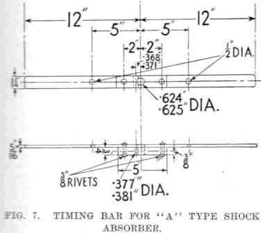
Fig.7. TIMING BAR FOR A-TYPE SHOCK ABSORBER
The holes that are shown are to be used for bolting the shock absorber to the board and a number of holes are necessary so that the various types of shock absorber can be bolted to the board in the same position that they occupy on the car from which they have been removed for test and so that the regulating valve is at the top in each case, and can thus be readily adjusted.
Timing Bars
In Fig. 7 the Timing Bar for testing the small or “A” type shock absorber is shown. It will be seen that this is made from a flat steel bar 24″ long, 1 ¼” wide, and ⁵⁄₁₆” thick.
In Fig. 8 a similar bar is shown for use in timing the larger or “B” type of absorber. It will be noticed that this bar is slightly different from the “A” type bar, in that it has a stud at each end to act as a stop against the hardwood blocks on the testing board.
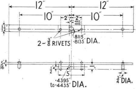
Fig.8. TIMING BAR FOR B-TYPE SHOCK ABSORBER
How the Test is made
In the case of shock absorbers having the arm fixed to the spindle by a cotter pin, the latter is driven out and the arm removed. The timing bar (either for “A” or “B” according to type) is then placed on the spindle, to which it is fixed by the cotter pin. In the case of units having splined shafts the lever arm of the shock absorber itself is generally used as the timing bar, to avoid the necessity of withdrawing the arm.
The timing bar or shock absorber arm, as the case may be, is then moved upwards as far as it will go, and the complete assembly (that is, shock absorber and timing bar), bolted on the timing board in such a manner that the timing bar (or arm) is close up against the top hardwood stop. It should be mentioned that the timing board can be held in the jaws of a vice at its lower end, but a better arrangement is to have it permanently fixed to a wall by angle brackets at the back. It will be noticed from Fig. 6 that the timing bar or arm will move through 100 degrees between its top position and its bottom position, where its motion will be arrested by the bottom hardwood stop.
From the upper pin on the timing bar or from a similar pin at the end of the shock absorber arm, the necessary weight is suspended. The timing bar or arm of the shock absorber, as the case may be, is then held firmly against the upper hardwood stop, with one hand, whilst the other hand manipulates a stop watch. The bar is released and the stop watch started at the same tinge, and the time taken for the weight to fall while the bar or arm is moving through 100 degrees, recorded. It is advisable to make three tests in each case, and to take the mean. If the time does not agree with that marked on the shock absorber, the latter must be adjusted in accordance with instructions previously given, until the timing test is exactly the same as that recorded by the makers.
It should be noted that when a timing bar is not used and the weight is suspended from a stud or bolt at the end of the shock absorber, unless the distance between the centre of the spindle and the centre of bolt on the arm is exactly 5″ in the case of the “A” type, and 10″ in the case of “B” type, the weight can either be altered accordingly, so that the product of the distance between these two points and the weight will be 100 in the case of the “A” units, and 200 in the case of the “B” units, or the alternative method given below used.
For example, supposing that the distance between the centre of the spindle of the shock absorber and the centre of the bolt at the end of its arm, from which the weight is suspended, is 5 ¼” instead of 5″, then the weight will have to be 19 ¹⁄₂₁ lb., or approximately 19 lb. 3/4 oz., because this weight, multiplied by 5 ¼, will give the necessary 100 lb. in. torque.
An alternative method of testing the shock absorber when the distance between the centre of the spindle and the centre of the bolt on the shock absorber arm is either more than 5″ or 10″ as the case may be, is to measure from the centre of the spindle along the shock absorber arm a distance of 5″ [127mm] in the case of “A” type, and 10″ [254mm] in the case of the larger types, and from this spot to hang the 10 lb. [4.5kg] or 20 lb. [9kg] weight and carry out the test just as if a timing arm were being used.
The above taken from:
‘The Service Station and Mechanics Manual’ by George George
Published by Angus & Robertson Ltd. Sydney 1940
[Ed: E.A. Gailitis 5/9/2022 elmar@gailitis.com]