One of the great pleasures of life in the countryside of the Breede River Valley, in South Africa’s Western Cape Province, is that it is one of SA’s premier wine growing areas. With that comes the opportunity to use Tickford coupe SA 0507 as a wedding car, because several of the wineries are well set up as wedding venues – see attached picture of owner and car ! Added to this is the car’s charity fund-raising power, built into the hire charge.
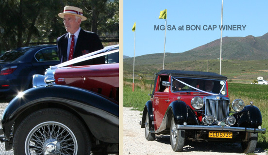
SA 0507 as a wedding car
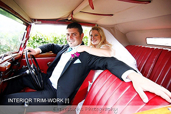
Happy couple in the wedding car – SA 0507
However this activity does have its hazards : on a recent occasion, I found I could not release the fly-off handbrake to drive away. Passengers had to dismount, I had to place a brick behind a rear wheel, then release the handbrake and was able to set off.
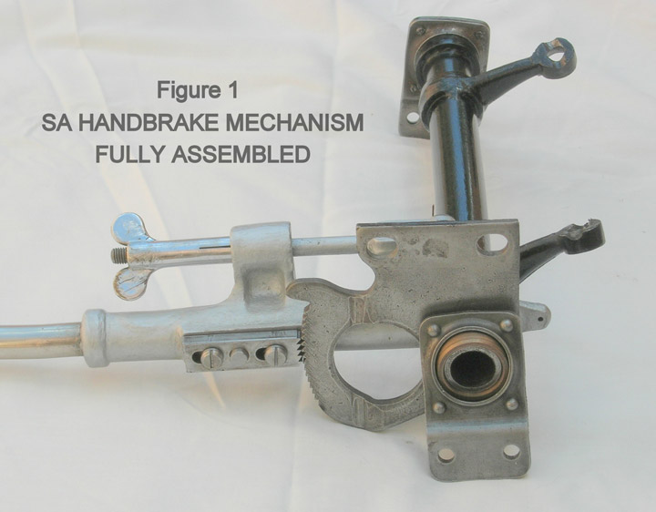
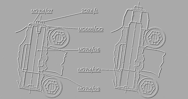
Fig. 1 – Fully assembled SA handbrake mechanism
Chassis distortion from parking on very uneven ground? Super-tensioned hand-brake cables from car loading? More likely a fault in the fly-off mechanism was my conclusion. The SA workshop manual makes no mention of the mechanism at all and “Blower” merely devotes two paragraphs to its adjustment – almost certainly not my problem here. So, remove driving seat, floor-board and leather boot round mechanism. Then un-bolt brake cross-shaft from chassis, strip, clean and examine. Figure 1 shows the mechanism fully assembled and Figure 2 shows it reduced to its component parts.
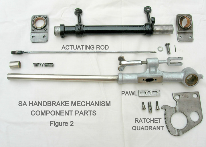
Fig. 2 – SA handbrake mechanism component parts
The cause of the problem immediately became obvious: the screw thread in the cylindrical peg was stripped to almost nothing. (This peg, shown in the components picture between the two screws which guide the pawl movement, drives the rectangular toothed pawl down to engage with the fixed ratchet quadrant).
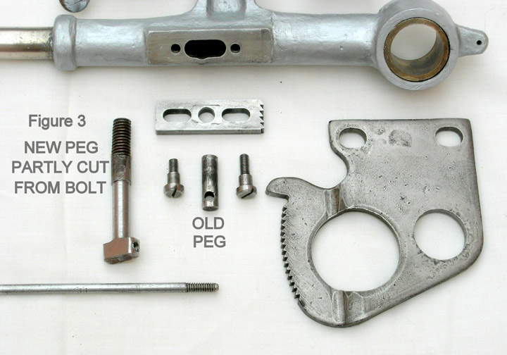
Fig. 3 – New peg partly cut from bolt and old peg
Hence the long spring-loaded actuating rod, attached to the operating knob at the top of the brake lever, was very loose in the peg and could barely drive it up or down. The leverage between rod and peg is considerable ; even when new, the threads could be expected to start wearing loose rapidly. Only 3-4 turns actually engage with the rod – a clear design weakness.
Clearly a new peg had to be made, but to an improved design with long life in mind. Fortunately, the threads on the rod were almost unworn, so it made sense to utilise more of them. Figure 3 shows a half-way stage in the manufacture of the new peg, “carved” from a 10mm bolt so that a threaded hole could run laterally through the bolt head, while the bolt stem formed the peg. Figure 4 shows the finished new peg threaded onto the rod and in position on the pawl.
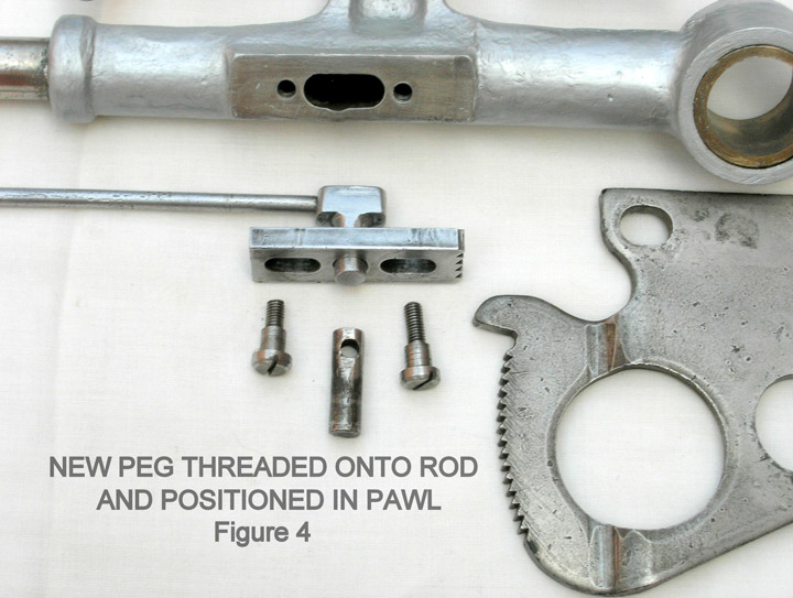
Fig. 4 – Peg threaded onto rod and positioned in pawl
Inevitably some minor fettling and adjustment were needed on re-assembly but the end result is a nice solid feel to the actions of applying and releasing the hand-brake. The new part is a small one but a light solution to a heavy problem!