by John Bannister
This is a job that anyone with reasonable practical ability and a good set of tools can complete successfully, however it should be noted that the MG SA has a “wet clutch” lubricated with engine oil, so it differs somewhat in basic design from the more familiar dry-clutch models.
Print off and follow these notes during the dismantling process, adding any extra comments alongside and take Digital Photos at frequent intervals to aid re-assembly. It is also good practice to “bag up” all nuts, bolts, screws and other loose items immediately on removal, label up and store carefully!
Refitting a new clutch will take about 15-20 hours depending on any other work done and how easy it is to remove seized-up components. Having a second person to assist will speed up and simplify the whole exercise.
(Please read Notes 36 & 37 below and this whole Article BEFORE starting).
- Raise the car onto axle stands and check carefully to ensure stability. (If you are lucky enough to have an inspection pit, it will need to be one with removable cross-beams able to support a trolley-jack underneath the bell-housing when separating the gearbox from the engine).
- Remove the Rear Seat Swab and disconnect the Batteries underneath.
- Slide the Front Seats fully back off the end of their runners, and remove.
- Unscrew and remove all 4 front seat Runners. Label each one.
- Unscrew the Rubbing Strip from the lower edge of each front door frame.
- Remove all Carpets front and back and the Under-Felt. Label up each item.
- Remove all bolts and screws holding the front Floor Boards to the Chassis. An Assistant will be required to grip the Floor Board nuts from below and due to corrosion or seizure this may necessitate liberal application of anti-seize fluid or even partial or complete grinding away of the exposed bolt threads below to allow final removal.
- Lift out both front Floor Boards, noting which is the upper face for refitting.
- Undo the fixing screws and remove the Plastic Shield from the top of the Gearbox. (This is fragile, but a stronger replacement is available from SVW Spares if needed).
- To remove the starter motor, loosen the three holding bolts, temporarily re-connect the battery cables, select Neutral and pull the starter knob a few times until the starter has visibly loosened. Disconnect the battery, remove both electrical wires from the starter and the starter knob cable. Take the weight of the starter with rope as it is heavy, then remove the holding bolts and pull the starter away from the bell housing. Catch any oil drips and lift it upwards through the chassis gap.
- Select 4th gear, disconnect the Gear Lever remote linkage, undo the bolts and remove the complete gear lever assembly.
- Undo the fixing screws and remove the metal Prop-Shaft cover.
- Mark both front Prop-Shaft flanges using pop marks or Tippex before splitting, to enable them to be re-fitted in the same position for correct balance on re-assembly! Tie up the forward end of the prop-shaft out of the way.
- Do not loosen either the Exhaust Pipe Connections, or the 2 front or the 2 intermediate engine support bolts.
- Undo the Jackall and foot brake oil reservoir fixing bolts and support both. Do not disconnect any hydraulic piping!
- Undo the rubber Muffs on the Steering Column, the Clutch and the Brake Pedal assemblies. Slide these away and temporarily tie-up away from the angled floor Ramp Plate.
- Disconnect the Accelerator, Clutch & Brake Pedal linkages and the Accelerator pedal stop. Temporarily remove these Pedal Assemblies and tie out of the way.
- Undo the Dipper Switch from the floor.
- Undo all the fasteners holding the angled floor Ramp Plate and move the Ramp Plate to one side, taking care not to trap any cables. Tie up temporarily.
- Carefully remove the soft rubber insulation from the top of the Gearbox.
- Disconnect the Reversing Light cables from the top of the Bell Housing and temporarily tie them out of the way.
- Drain the oil from the Gearbox and remove the oil level Dipstick.
- Use a Trolley Jack for support under the Clutch Bell-Housing and adjust just high enough to take the weight of the Bell Housing and Gearbox!
- Undo the 2 rubber doughnuts on the Engine/Gearbox Rear support plate, dismantle completely and remove.
- The Speedometer Cable connection to the gearbox can now be accessed. Slacken this connection and remove the cable from the Gearbox, taking care not to lose the small gasket. Tie up temporarily out of the way.
- If possible, knock out the pin which holds the clutch operating arm onto the operating shaft and remove the arm. This tapered pin can only be removed in one direction therefore access to do this may be impossible. Photograph the arm before removal to ensure it is re-fitted correctly.
- Removal of the Gearbox is easier if the top cover is taken off. If this is done, take great care to prevent the gear selector Detent Balls and Springs from either dropping out and being lost on the floor, or falling directly into the gearbox internals or tail-extension cavity! Fitting a temporary cardboard or plywood lid held by the six lid nuts is recommended.
- Ensure the Trolley Jack is safely supporting the weight of the Gearbox, wrap safety slings loosely around the gearbox and undo all the bolts holding the Bell Housing to the engine.
- Be ready to catch about a cup-full of oil from the joint and carefully ease the Gearbox/Bell Housing backwards away from the Engine.
- If the Clutch Lever has been removed in-situ, it will be possible to slide the Gearbox Assembly rearwards until the input shaft is free from the engine. The clutch operating shaft will “self-rotate” (Mark the final position of the Clutch Shaft for re-assembly) and then lift the gearbox upwards clear of the Chassis. Two people will be needed to take the weight.
- If the Clutch Operating Lever is still attached to the Bell Housing, then the whole Gearbox/Bell Housing Assembly must be rotated clockwise 90 degrees (when viewed from the rear) whilst it is being slid backwards from the engine. This will allow the lever to negotiate the Sump and Chassis. The Clutch lever shaft will “self-rotate” during withdrawal of the gearbox to allow disengagement of the Clutch Actuating Forks from behind the Clutch Release Bearing. Note the direction of rotation and the final position of the actuating arm. Take a photo, as this is critical for the re-assembly start position. (See Note 43).
- The Gearbox can now be inspected and overhauled if necessary.
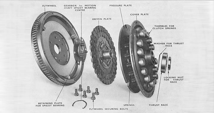
- The Clutch and Flywheel Assembly is now exposed. To dismantle the Clutch, mark the plate and flywheel for correct re-assembly location, and loosen the 12 Clutch Pressure Plate holding bolts in a diagonal sequence, one-turn-at-a-time to avoid bending the plate, until they are all loose. Pressure from the springs should be enough to release the Clutch Pressure Plate Assembly, which can now be removed.

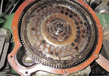
Worn clutch plate
- Carefully remove the large Circlip from the three pins which protrude through the cork-lined Driven Plate and remove the worn plate. (These circlips are very hard to source if damaged or lost!)
- Clean off all the Clutch components and gauze filter screens. Inspect the springs, the general condition of the Pressure Plate and the Clutch Release Bearing. Overhaul or replace if worn. The release bearing can be removed by undoing the circular retaining nut.
- Obtain a new Clutch Driven Plate from a reputable source and check that it is an identical replacement. VA wet clutch plates are not compatible and obviously neither are VA and WA dry plates. The new plate will come fitted with specially prepared high-quality corks accurately machined to the correct projection on each side of the plate. (In view of all the work involved in replacing the clutch, attempting to re-cork and machine a clutch plate yourself is NOT recommended).
- Leave the new Cork Clutch Plate overnight in a bath of engine oil to ensure the corks are fully saturated before re-fitting. This reduces initial wear whilst the cork faces are bedding in, thereby significantly increasing clutch life.
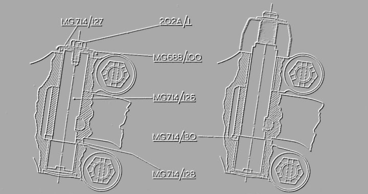
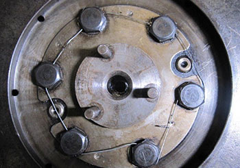
Clutch Plate support assembly
- Check wear in the Spigot Bearing supporting the three-pin Circlip flange in the centre of the Flywheel. This is a flexible “floating” bearing, but if it feels “rough” when gently rotated by hand, then remove the 6 bolts on the bearing cover flange and renew the bearing (The code will be stamped on it for re-ordering), replace the flange back in the same position on the Flywheel, tighten the 6 bolts and re-fit new locking wire.
- It is now time to start the Clutch rebuild, but do check all the major items first whilst they are removed as this is the only opportunity to repair or maintain them whilst everything is apart! Bell Housing oil leaks can be resolved (by fitting new Clutch Operating Shaft bushes) as can any problems associated with Starter Motor oil leaks and Gearbox issues.
- Re-assembly is carried out in reverse order to that detailed above.
- Ensure that the new oil-soaked Cork Clutch Plate is fitted the correct way round! Usually a note is stamped on one face “Flywheel Side”. The protruding spline must be on the side away from the Flywheel! (Remember to fit the 3-pin Circlip correctly and very carefully!)
- On assembly, the Cork Clutch Plate must be centralised before any Clutch Pressure Plate bolts are tightened. This can be done by making up a Mandrel using a wooden or metal circular bar small enough to fit into the flywheel spigot bearing. Insulating Tape can then be wrapped round the bar to increase its diameter to ensure a good fit. Several thicknesses of tape will be needed to increase the Mandrel diameter sufficiently to match the internal diameter of the Clutch Plate spline. Once centralised, align the location marks on the pressure plate and flywheel, tighten the 12 Pressure Plate bolts successively in sequence on alternate sides to evenly close up the whole Clutch assembly, then remove the mandrel.
- Clean off the face of the Bell Housing flange and either fit a new Gasket or apply plenty of Gasket sealant, support the Bell Housing/Gearbox assembly on the Trolley Jack and carefully offer the gearbox input shaft back into the Clutch Assembly Spigot Bearing, ensuring correct alignment for height and squareness to the engine. (Safety Slings, loosely fitted to support the Gearbox are recommended). Check before fitting the gearbox to see if it looks possible to re-fit the taper pin in the clutch operating lever with the gearbox in its finally fitted position. If not, the pin will have to be fitted now and the Gearbox rotated 90 degrees clockwise onto its side and then rotated back anticlockwise as it is offered into position. Important! The Clutch operating shaft MUST be rotated fully (see note 31) so that the forks engage BEHIND the Clutch Release Bearing BEFORE the gearbox is pushed forward into position! The engine Crankshaft will also need to be rotated manually before the gearbox can be pushed fully home using the Starting Handle (or the gearbox put into 4th gear and the rear flanged turned) to rotate the input shaft splines to match those in the new clutch plate. The Spigot Bearing entry is chamfered and the bearing itself is of the “floating” design, so that mating of the gearbox input shaft into the Spigot should be straightforward!
- Continue the re-assembly in reverse order, remembering to refit all the detent balls and springs under the gearbox cover plate. Then, either fit an improved speedo connection (from SVW spares) to the gearbox or fit a new seal instead as the old one invariably leaks, also check that the prop-shaft flanges are re-assembled with the marks lined up to ensure this remains balanced. Re-fill the Gearbox with 2.25 pints of suitable gearbox oil. (Penrite is a good brand). The starter Motor will need a new gasket, or Gasket Sealant applied, before refitting.
- Finally, set the clutch pedal travel by adjusting the nut on the Clutch actuator linkage under the car to give 1 inch of free-play at the pedal foot pad, then adjust the clutch floor stop to the point where the clutch just stops spinning when the pedal is fully depressed. i.e. There should be no “gear crunch” when the clutch has been depressed fully and first or second gear is gradually selected (start with approx 4.5 inches full travel, including the 1 inch of free-play.)
- Treat the clutch with great care when driving the car initially. The corks will bed-in within a hundred miles or so and will give a much prolonged life thereafter if treated gently at the start!
Have fun driving your SA. Like the rest of the MG SVW Range they are magnificent cars to own and enjoy!
(I would like to thank Gary Perry and Jim Andrews for their advice with this Article).